Installing DC Power Entry Modules | 31
Step Task (continued)
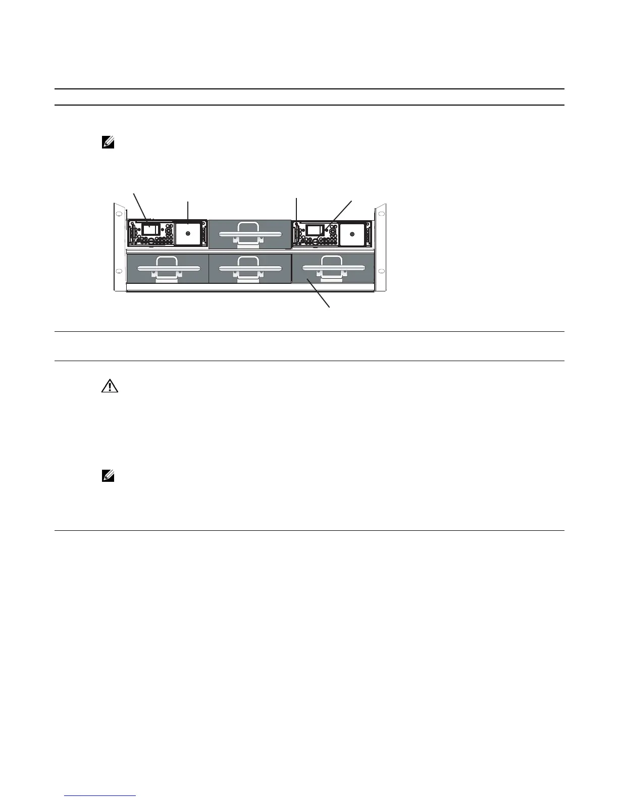
4 Slide the PEM into either power slot 0 or 2 (see
(Figure 8-2)
. If you are installing redundant PEMS, install in both
slots 0 and 2.
NOTE: Fill all empty slots with blank panels (CC-C-BLNK-PWR).
Figure 8-2. Insert 2 DC PEMs in Slots 0 and 2
5 Secure the PEM in place by tightening the retaining latch on each module so that the arrow points down
(Figure 8-1)
.
6 Secure the chassis ground connection:
WARNING: You must complete the ground connection before proceeding with any other PEM connection.
Locate the chassis ground connector stud on the PEM front panel (see
Figure 8-3
). It is the single stud below the
safety cover.
Remove the nut and washer from the ground stud.
Apply a coat of anti-oxidant paste to the connector stud, if required.
Install the grounding cable. This cable is typically green or green and yellow.
NOTE: Termination points require UL-listed 1-hole lug with a 1/4-inch hole.
Replace the washer and nut on the stud.
Secure the nut with a nut driver or torque wrench (not to exceed 4 ft/lbs).
Connect the opposite end of the grounding cable to the appropriate nearest grounding.
7 Remove the outer nuts and washers from each of the remaining studs.
BLNK
fn00012lpp
fn003lp
BLNK
fn003lp
BLNKBLNK
Safety Cover
Over-Current Switch
Retaining Latch
Handle
Power Supply Blank