Removing and Replacing Components | 43
To remove and replace C150 line cards:
Removing and Replacing an RPM
WARNING: After removing an RPM, place a panel blank in the empty slot before powering up the chassis.
Blanks are required to control airflow and electromagnetic interference.
NOTE: The C150 requires at least one RPM to operate. The system enters a software-defined power-down
state if you remove the only RPM.
To remove and replace a C150 RPM:
Step Task
1 Unplug the network interface cables connected to the line card.
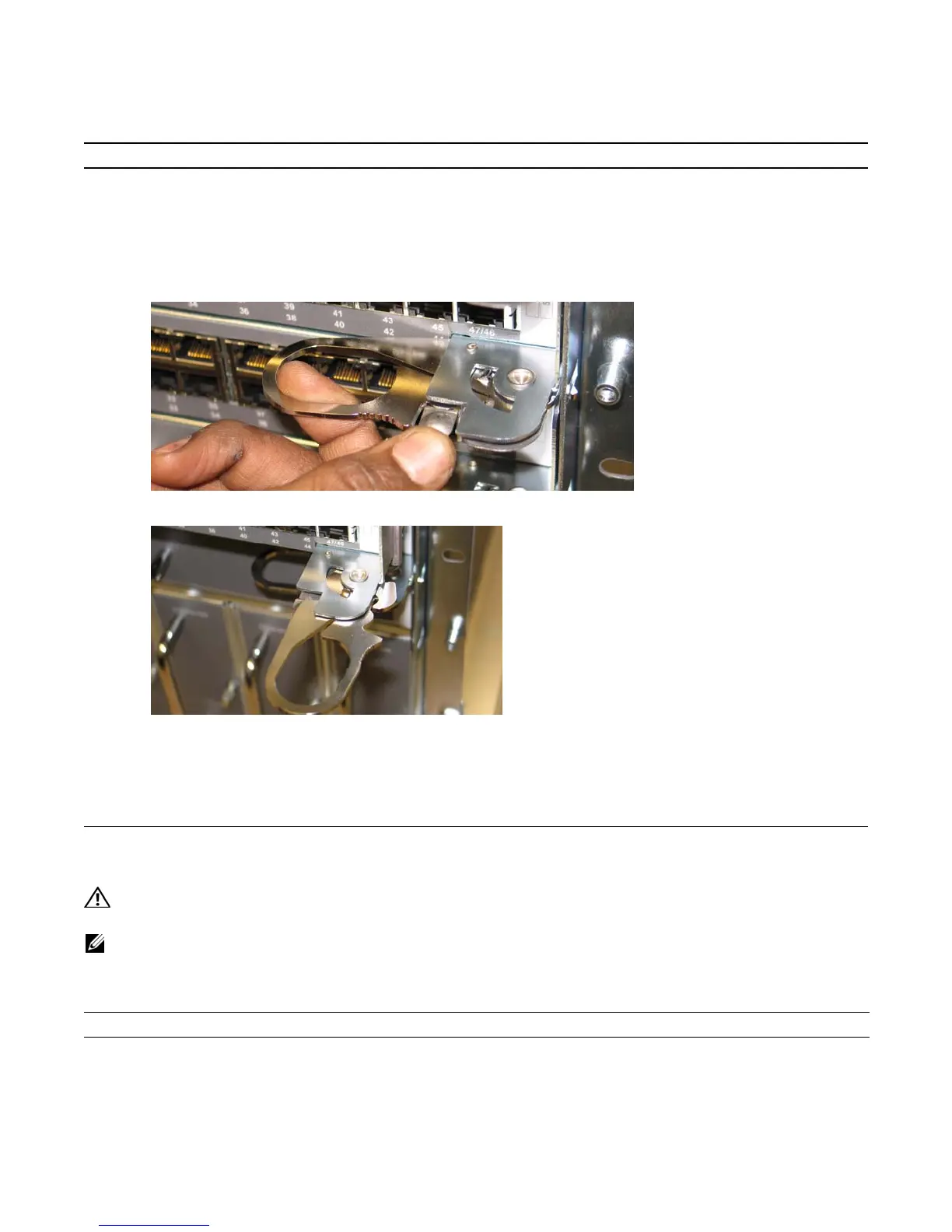
2 Extend the left and right card levers by first pressing gently down on the thumb tabs (
Figure 11-1
) in the ejector
levers and then pulling the ejector levers simultaneously until they are in the open position, as shown in
Figure 11-2
.
Figure 11-1. Depressing the Thumb Tabs
Figure 11-2. Extending the Levers
3 Pull the card by the card levers until it is out of the slot. Avoid touching the printed circuit board and connector
pins.
4 If you are not replacing the card immediately, install a blank panel.
5 If you are replacing the card, follow the instructions in
Installing RPMs and Line Cards on page 19
.
Step Task
1 Unplug any network interface cables connected to the RPM.