44 | Removing and Replacing Components
www.dell.com | support.dell.com
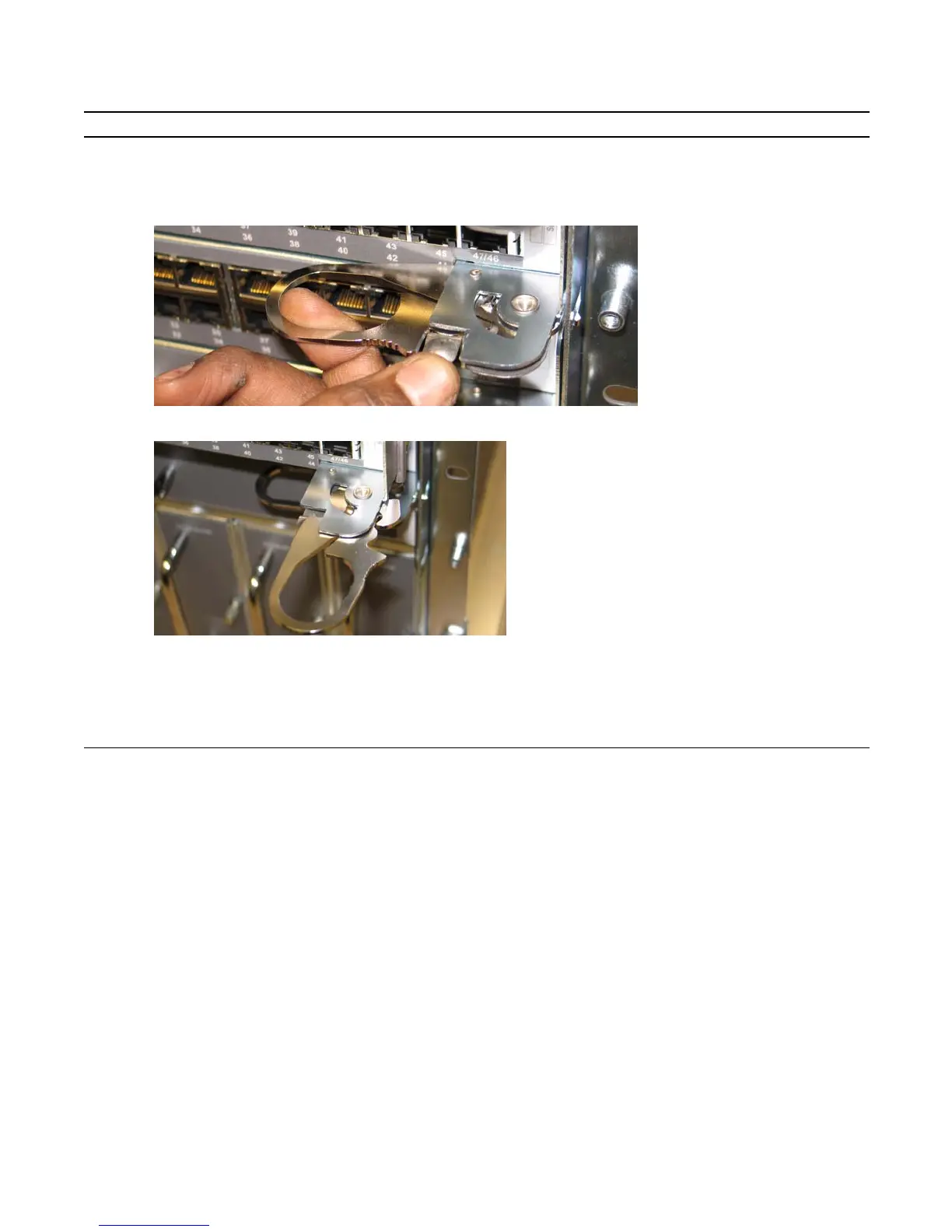
2 Extend the left and right card levers by first pressing gently down on the thumb tabs (see
Figure 11-3
) in the ejector
levers and then pulling the ejector levers simultaneously until they are in the open position. See
Figure 11-4
.
Figure 11-3. Depressing the Thumb Tabs
Figure 11-4. Extending the Levers
3 Pull the card by the card levers until it is out of the slot. Avoid touching the printed circuit board and connector
pins.
4 If you are not replacing the RPM, insert an RPM blank panel.
5 If you are replacing the RPM, follow the instructions in
Installing RPMs and Line Cards on page 19
.
Step Task (continued)