Overview | 9
2
Overview
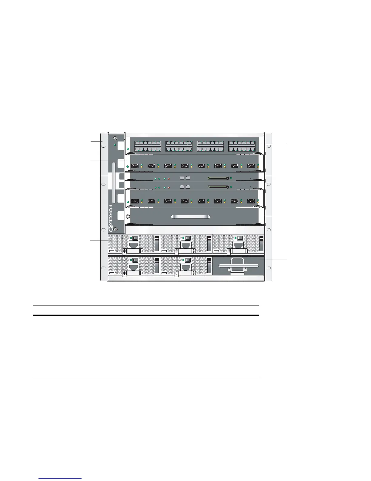
The C150 is a high performance switch/router. This 6-slot system contains two slots for Route Processor
Modules (RPMs) and four slots for line cards (
Figure 2-1
).
Figure 2-1. C150 Chassis (Front View)
Table 2-1. C150 Component Requirements
Component Minimum Maximum Field-Replaceable
Backplane (factory installed) 1 1 No
Fan tray 1 1 Yes
RPM 1 2 Yes
Line card 1 4 Yes
AC Power Supply 2 6 Yes
DC Power Entry Module 2 6 Yes
BLNK
Reset
RJ-45
Console
Compact Flash
Status Master
SFM
ACTIVE
Alarm
Reset
RJ-45
Console
Compact Flash
Status Master
SFM
ACTIVE
Alarm
BLNK
0
1
2
3
R0
R1
Power Supply Unit
Fan Tray
Front Mount Bracket
-Port 10G Fiber Line Card
Route Processor
Module
Line Card Blank
Power Supply
Unit Blank
48-Port 1G Line Ca
fnD0001m