32 | Installing DC Power Entry Modules
www.dell.com | support.dell.com
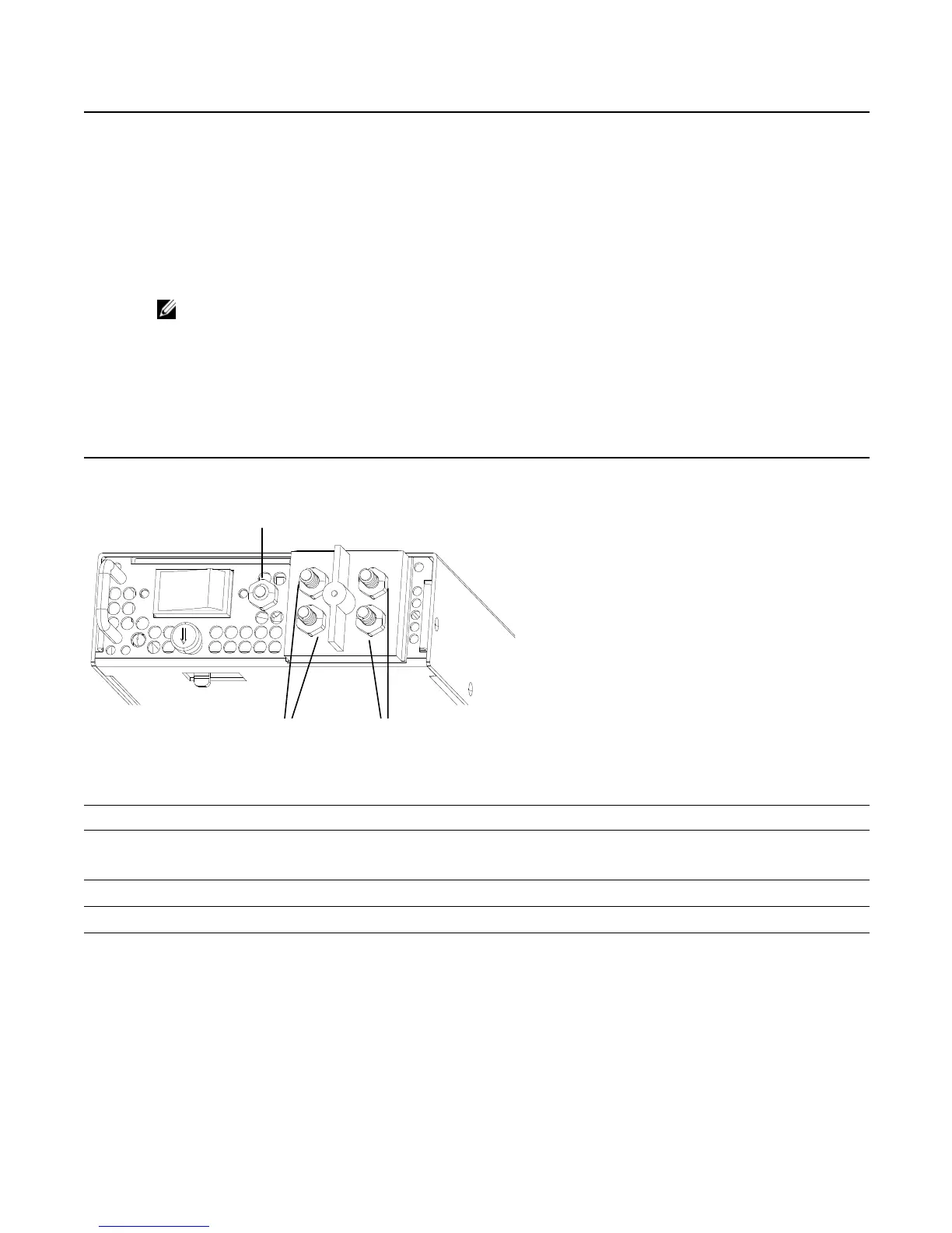
Figure 8-3. Grounding
8 Connect the -48 VDC and Return cables from each PEM to the remote power sources.
Verify that the remote power source is in the OFF position.
Locate the appropriate studs on the PEM front panel.
• The two right-handed studs (furthest from the GND) are the return (+48V DC) connection. The cable
attached to these studs is typically red.
• The two left-handed studs (closest to GND) are the -48 V DC connection. The cable attached to these studs
is typically black.
NOTE: Power cables must be terminated only with a UL-listed 2-hole lug to accommodate 1/4-inch studs with
3/4-inch spacing.
Apply a coat of anti-oxidant paste to the connector studs, if required.
Replace the washers and nuts on the studs.
Route the terminated cables out toward the rack rail.
Cables will route down toward the floor. You can then route them as best suits your environment.
Secure the nuts with a nut driver or torque wrench (not to exceed 4 ft/lbs).
Step Task (continued)
9 Replace the safety cover and tighten the captive screw.
Note that the safety cover can be rotated to accommodate system configurations.
10 Turn the Over-Current Protector to the ON position (
Figure 8-1
).
11 Turn the remote power source (the circuit breaker panel) to the ON position.
Step Task (continued)
Ground
Connector
Return (+48V)
Connectors
-48V Connectors