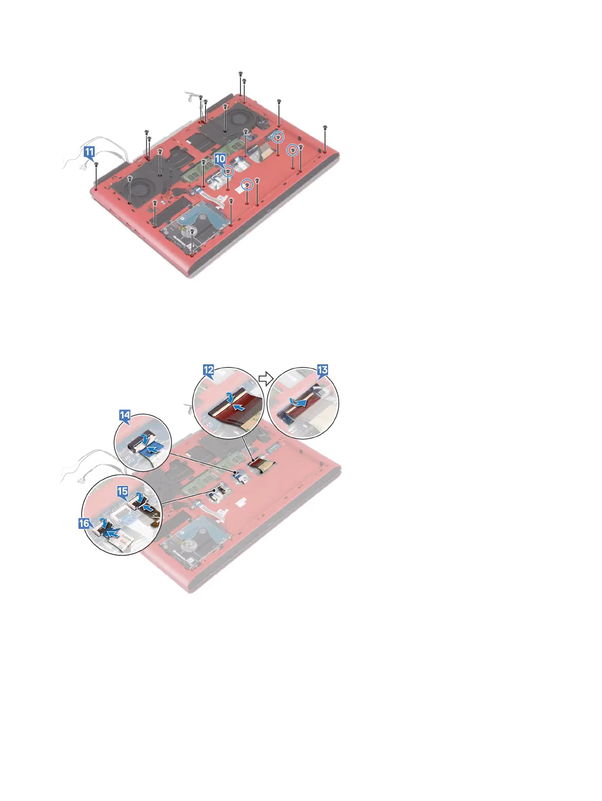
10 Replace the four screws (M2x3) that secure the computer base to the palm-rest assembly.
11 Replace the 19 screws (M2.5x6) that secure the computer base to the palm-rest assembly.
12 Slide the keyboard cable into the connector on the system board and close the latch to secure the cable.
13 Adhere the tape that secures the keyboard cable to the system board.
14 Slide the touchpad cable into the connector on the system board and close the latch to secure the cable.
15 Slide the keyboard-backlight cable into the connector on the system board and close the latch to secure the cable.
16 Slide the power-button board cable into the connector on the system board and close the latch to secure the cable.
17 Adhere the display cable to the computer base and route the display cable through the routing guides on the computer base.
18 Connect the display cable to the system board.
19 Align and place the display-cable bracket on the computer base.
20 Replace the screw (M2x3) that secures the display-cable bracket to the computer base.
21 Route the antenna cables through the routing guides on the computer base.
22 Adhere the camera cable to the computer base.
23 Connect the camera cable to the system board.
Replacing the computer base
41
 Loading...