Configuring VLANs 603
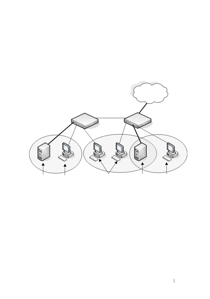
Figure 22-26 shows the network topology for this example. As the figure
shows, there are two switches, two file servers, and many hosts. One switch
has an uplink port that connects it to a layer 3 device and the rest of the
corporate network.
Figure 22-26. Network Topology for Port-Based VLAN Configuration
The network in Figure 22-26 has the following characteristics:
• Each connection to a host represents multiple ports and hosts.
• The Payroll and File servers are connected to the switches through a LAG.
• Some of the Marketing hosts connect to Switch 1, and some connect to
Switch 2.
• The Engineering and Marketing departments share the same file server.
• Because security is a concern for the Payroll VLAN, the ports and LAG that
are members of this VLAN will accept and transmit only traffic tagged
with VLAN 400.
• The Sales staff might connect to a port on Switch 1 or Switch 2.
VLAN 400
Payroll
Payroll
Server
Shared File
Server
Payroll
Hosts
Marketing
Hosts
Engineering
Hosts
Switch 1 Switch 2
VLAN 100
Engineering
VLAN 200
Marketing
LAN/WAN
 Loading...