622 Configuring the Spanning Tree Protocol
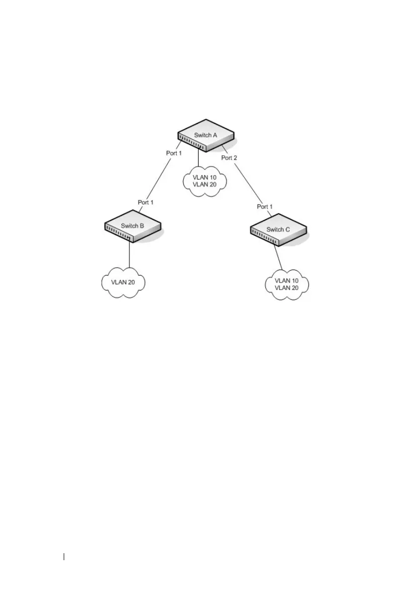
Figure 23-2 shows the logical single STP network topology.
Figure 23-2. Single STP Topology
For VLAN 10 this single STP topology is fine and presents no limitations or
inefficiencies. On the other hand, VLAN 20's traffic pattern is inefficient. All
frames from Switch B will have to traverse a path through Switch A before
arriving at Switch C. If the Port 2 on Switch B and Switch C could be used,
these inefficiencies could be eliminated. MSTP does just that, by allowing the
configuration of MSTIs based upon a VLAN or groups of VLANs. In this
simple case, VLAN 10 could be associated with Multiple Spanning Tree
Instance (MSTI)1 with an active topology similar to Figure 23-2 and VLAN
20 could be associated with MSTI 2 where Port 1 on both Switch A and
Switch B begin discarding and all others forwarding. This simple modification
creates an active topology with a better distribution of network traffic and an
increase in available bandwidth.

 Loading...