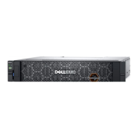
Figure 16. 5U84 controller enclosure—rear panel components
1. Controller module A 2. Controller module B
3. FCM 0 4. FCM 4
5. PSU 0 6. PSU 1
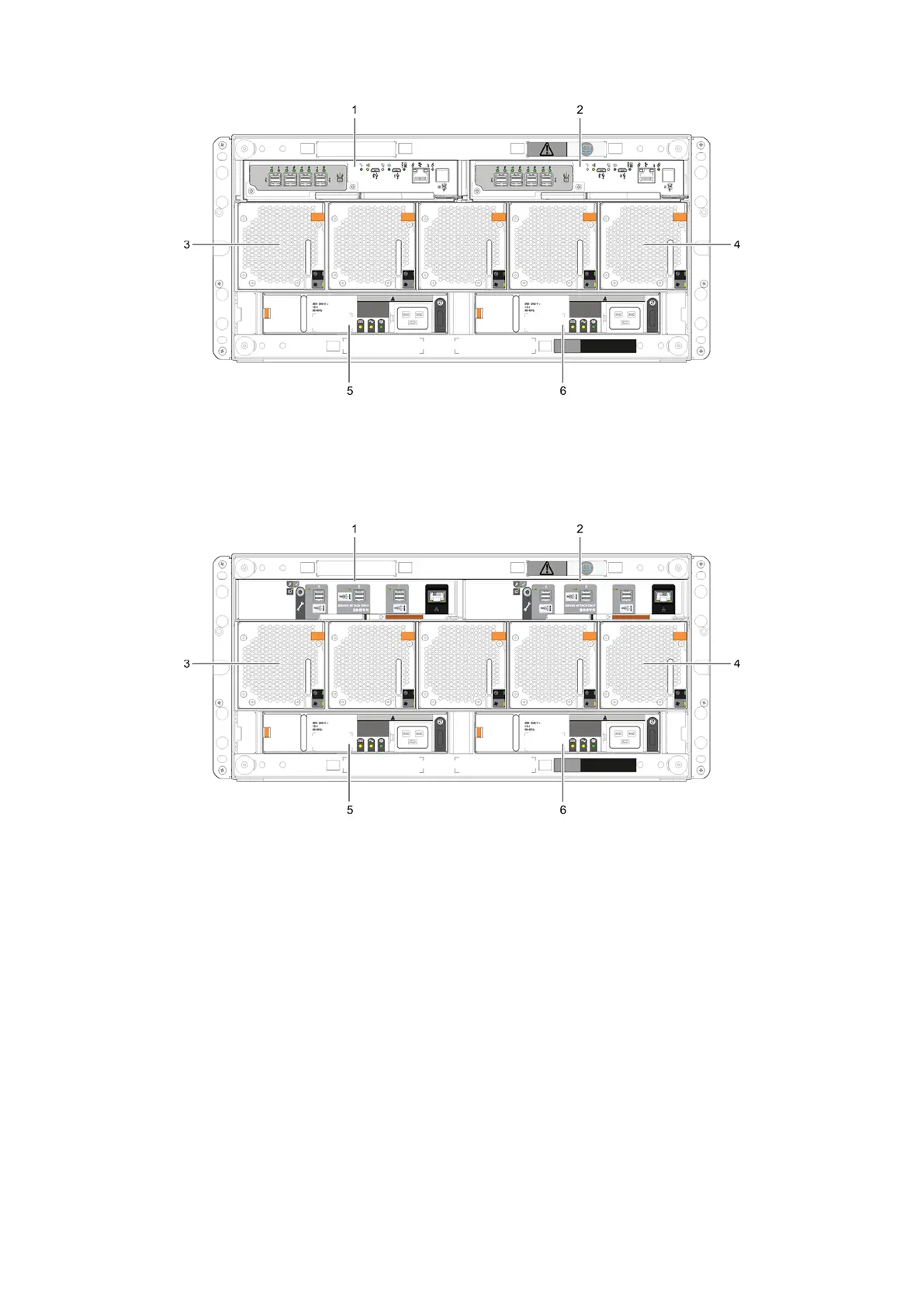
Figure 17. 5U84 expansion enclosure—rear panel components
1.
IOM A 2. IOM B
3. FCM 0 4. FCM 4
5. PSU 0 6. PSU 1
5U84 rear panel components
This section describes the rear-panel controller modules, expansion module, power supply module, and fan cooling module.
Controller modules
The 5U84 controller enclosure uses the same controller modules that are used by 2U12 and 2U24 enclosures.
The top slot for holding controller modules is designated slot A, and the bottom slot is designated slot B. The face plate details
of the controller modules show a module aligned for use in slot A. In this orientation, the controller module latch is shown at
the bottom of the module and it is in a closed/locked position. See 12 Gb/s controller module LEDs for information about the
indicators on the controller module.
16
Storage system hardware
 Loading...