• Reserved port R1 — Storage controller 2: port 1 to FC switch 1
3. Connect fault domain 2 (shown in blue) to fabric 2.
• Primary port P2 — Storage controller 2: port 2 to FC switch 2
• Reserved port R2 — Storage controller 1: port 2 to FC switch 2
Example
Figure 48. Storage System in Legacy Mode with Dual 16 Gb Storage Controllers and Two Fibre Channel
Switches
1. Server 1 2. Server 2
3. FC switch 1 (Fault domain 1) 4. FC switch 2 (Fault domain 2)
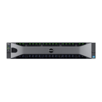
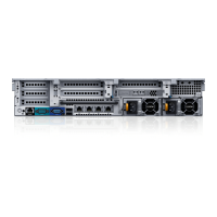
5. Storage system 6. Storage controller 1
7. Storage controller 2
Next steps
Install or enable MPIO on the host servers.
NOTE: For the latest best practices, see the Dell Storage Center Best Practices document located
on the Dell TechCenter (http://en.community.dell.com/techcenter/storage/).
Legacy Mode — Two Fibre Channel Fabrics with Dual 8 Gb 4-Port Storage Controllers
Use two Fibre Channel (FC) fabrics with legacy mode to prevent an unavailable port, switch, or storage
controller from causing a loss of connectivity between host servers and a storage system with dual 8 Gb
4-port storage controllers.
About this task
In this configuration, there are four fault domains, two FC fabrics, and two FC switches.
• Each fault domain contains a set of primary and reserve paths (P1-R1, P2-R2, P3-R3, and P4-R4).
• To provide redundancy, the primary port and corresponding reserve port in a fault domain must
connect to the same fabric.
• When MPIO is configured on the servers, the primary paths provide redundancy for an unavailable
server or storage controller port. The reserved paths provide redundancy for an unavailable storage
controller.
Connect the Front-End Cabling
61
 Loading...
