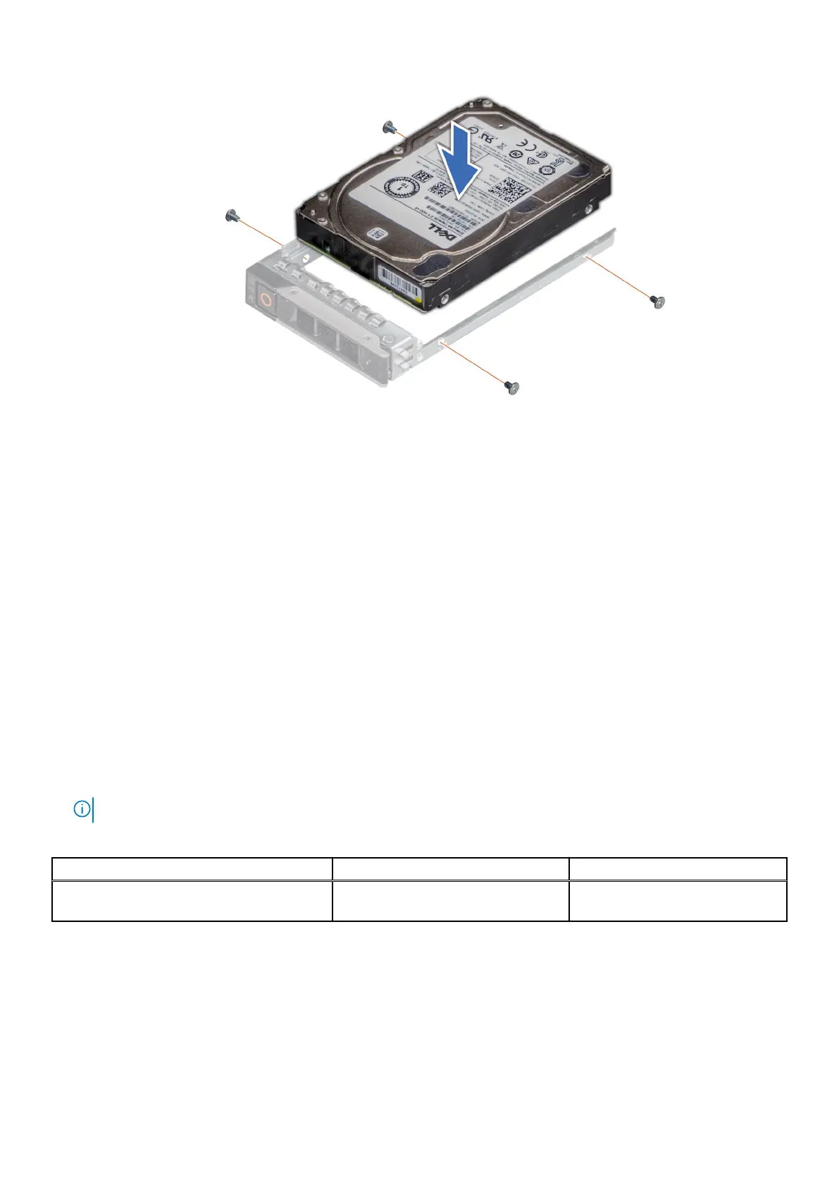
Figure 46. Installing a drive into the drive carrier
Identify a fault drive
Due to the replacement of sg_ses with PERCCLI on the CVM, the drive failure indicator will now blink in green instead of amber
on HBAs, such as the HBA 355. There is no other functional change.
Rear drive module
Removing the 2 x 2.5-inch rear drive module
Prerequisites
1. Follow the safety guidelines listed in Safety instructions.
2. Follow the procedure listed in Before working inside your system.
3. If required, remove the air shroud.
4. Remove the drives.
5. Disconnect the cables from the rear drive module.
NOTE: Refer to cable routing section for more information.
Table 34. Rear drive bay slot numbers
Configurations with two rear drives Bay0 slot numbers Bay1 slot numbers
12 x 3.5-inch SAS/SATA + 2 x 2.5-inch SAS/
SATA
Slot 0 and 1 N/A
Steps
1. Using a Phillips #2 screwdriver, loosen the captive screws that secure the rear drive module to the system.
2. Press the blue release tab and holding the edges lift the rear drive module away from the system.
74
Installing and removing system components