YDT-35 Operating and Servicing Manual
26 HL066(EN) ISSUE 1, 05/2015
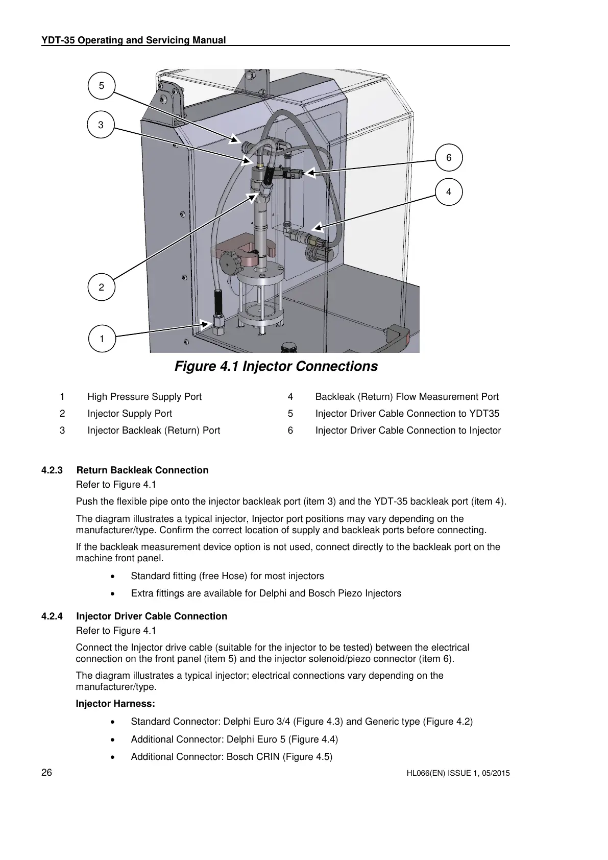
Figure 4.1 Injector Connections
4.2.3 Return Backleak Connection
Refer to Figure 4.1
Push the flexible pipe onto the injector backleak port (item 3) and the YDT-35 backleak port (item 4).
The diagram illustrates a typical injector, Injector port positions may vary depending on the
manufacturer/type. Confirm the correct location of supply and backleak ports before connecting.
If the backleak measurement device option is not used, connect directly to the backleak port on the
machine front panel.
Standard fitting (free Hose) for most injectors
Extra fittings are available for Delphi and Bosch Piezo Injectors
4.2.4 Injector Driver Cable Connection
Refer to Figure 4.1
Connect the Injector drive cable (suitable for the injector to be tested) between the electrical
connection on the front panel (item 5) and the injector solenoid/piezo connector (item 6).
The diagram illustrates a typical injector; electrical connections vary depending on the
manufacturer/type.
Injector Harness:
Standard Connector: Delphi Euro 3/4 (Figure 4.3) and Generic type (Figure 4.2)
Additional Connector: Delphi Euro 5 (Figure 4.4)
Additional Connector: Bosch CRIN (Figure 4.5)
Any technical intervention requires certified Hartridge training. Contact Hartridge Ltd for details.