YDT-35 Operating and Servicing Manual
36 HL066(EN) ISSUE 1, 05/2015
WARNING!
INVERSE POLARITY MAY DAMAGE PIEZO INJECTORS. MAKE SURE ALL PIEZO
INJECTORS USING THE GENERIC TYPE CONNECTOR (FIGURE 4.2) ARE
CONNECTED CORRECTLY.
When an Injector has been connected, the ‘Injector’ symbol appears at the bottom of the screen
(Figure 4.16).
Figure 4.16 ‘Injector Connected’ Symbol
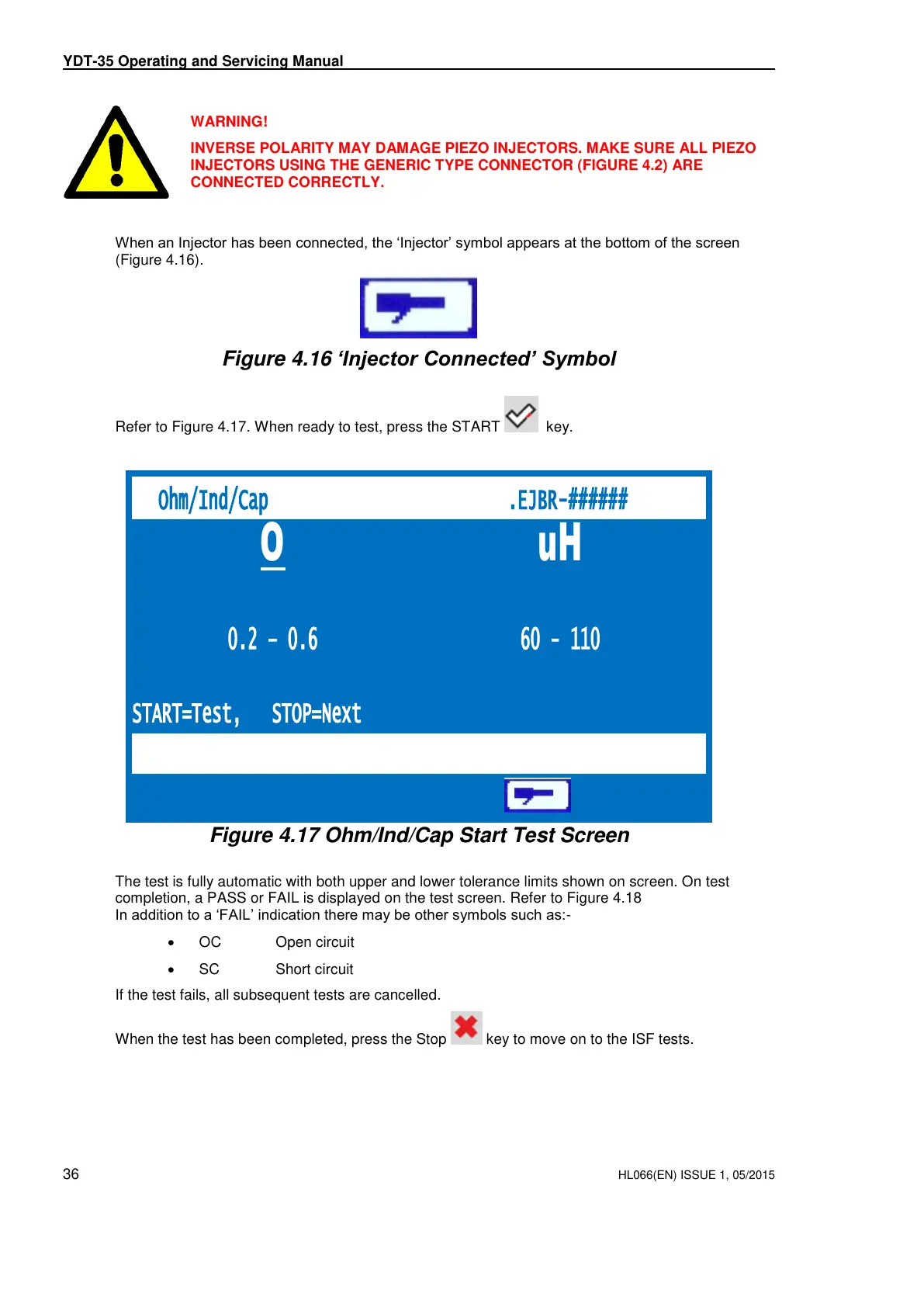
Refer to Figure 4.17. When ready to test, press the START key.
Figure 4.17 Ohm/Ind/Cap Start Test Screen
The test is fully automatic with both upper and lower tolerance limits shown on screen. On test
completion, a PASS or FAIL is displayed on the test screen. Refer to Figure 4.18
In addition to a ‘FAIL’ indication there may be other symbols such as:-
OC Open circuit
SC Short circuit
If the test fails, all subsequent tests are cancelled.
When the test has been completed, press the Stop key to move on to the ISF tests.
THIS IS AN UNCONTROLLED DOCUMENT downloaded by Lukas Matuska on 16 Feb 2016
Any technical intervention requires certified Hartridge training. Contact Hartridge Ltd for details.