Chapter 3 Wiring ASDA-A2R Series
3-66 Revision December. 2014
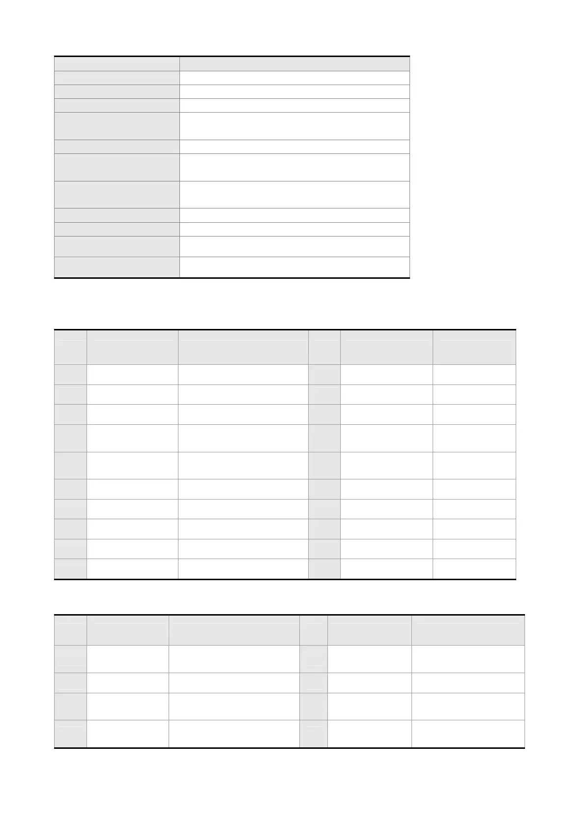
Item ASD-IF-EN0A20
Power Supply +5.0 V±5%
Current Consumption 250 mA Typ. 500 mA Max.
Frequency Response 2 MHz Max.
Analog Input Signal
(Sin, Cos, Ref)
Differential Input Amplitude: 0.4 to 1.2 Vp-p
Input Signal Level: 1.5 to 2.7 V
Pulse Input Signal +5 V
Input Signal of Hall
Sensor
+3.3 V
Output Signal
Position Data, Hall Sensor Information,
Warning
Output Type Serial data transmission
Weight Approx. 70 g
Operation Temperature
0 ~ 55 ℃
Storage Temperature
-20 ~+65 ℃
Pin Definition
20 pin Connector
PIN Definition Descriptions PIN Definition Descriptions
1
Reserved -
11
/OZ -
2
FPGA_TDI -
12
FPGA_TRST -
3
FPGA_TMS -
13
GND Power Ground
4
Drive_T-
Serial Communication
Signal Transmission (-)
14
5VD Power + 5 V
5
Drive_T+
Serial Communication
Signal Transmission (+)
15
GND Power Ground
6
FPGA_TCK -
16
5VD Power + 5 V
7
Reserved -
17
OB -
8
FPGA_TDO -
18
/OB -
9
OABZ_EN Pulse Output Enabled
19
OA -
10
OZ -
20
/OA -
26 pin Connector
PIN Definition Descriptions PIN Definition Descriptions
1
QEA_IN+ A-phase (+) pulse input
14
AGND
Sinusoid Power
Ground
2
QEA_IN- A-phase (-) pulse input
15
Motor_Temp -
3
QEB_IN+ B-phase (+) pulse input
16
HALL_W
W-phase Hall
Sensor Signal Input
4
QEB_IN- B-phase (-) pulse input
17
HALL_V
V-phase Hall Sensor
Signal Input
 Loading...
