Chapter 6 Control Mode of Operation ASDA-A2R Series
Revision December, 2014
6-41
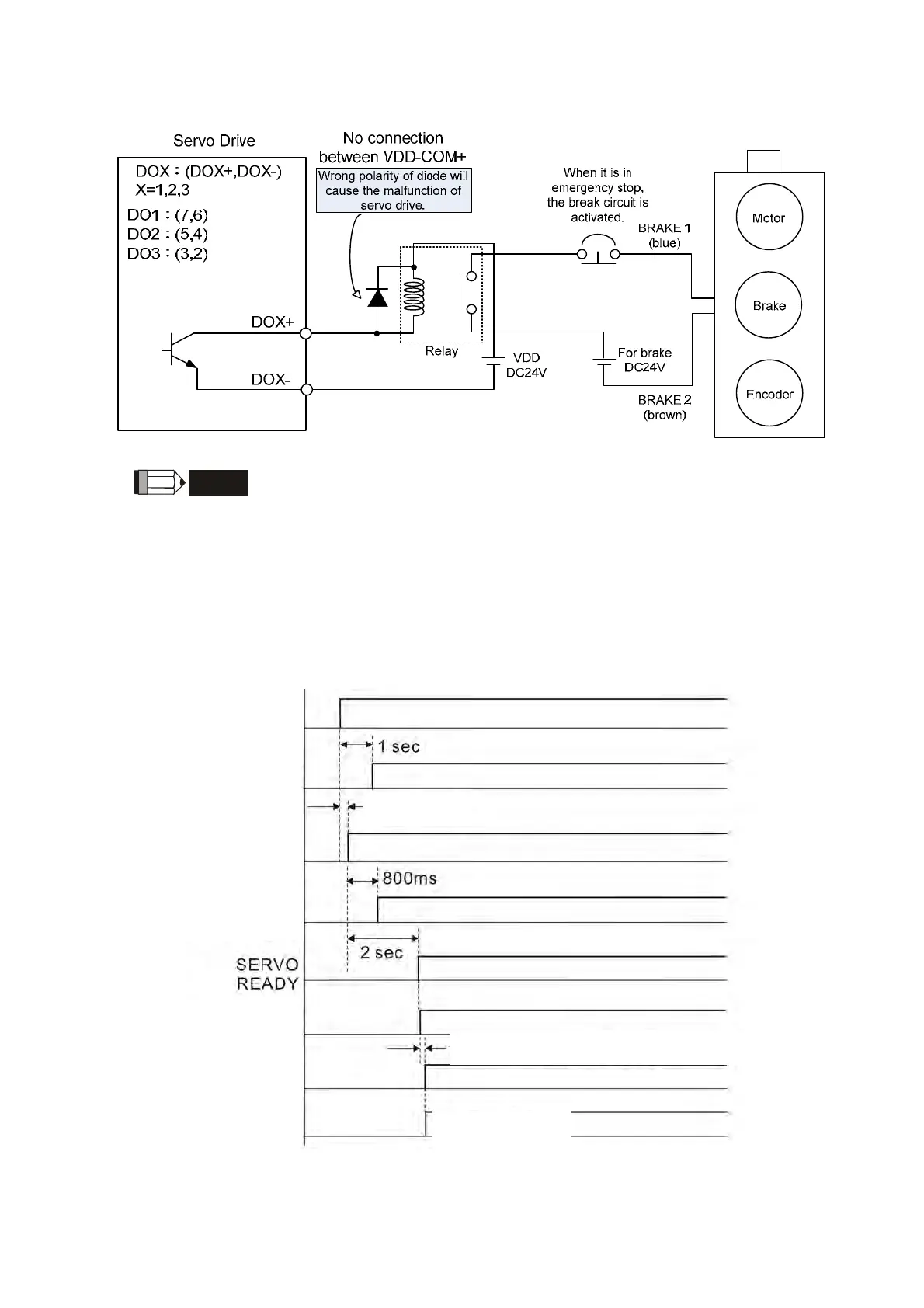
The wiring diagram of using mechanical brake:
NOTE
1)Please refer to Chapter 3, Wiring.
2
)The brake signal controls the solenoid valve, provides power to
the brake and enables the brake.
3
)Please note that there is no polarity in coil brake.
4
)Do not use brake power and control power (VDD) at the same
time.
Timing diagram of control power and main power:
Input is available
L1c, L2c
Control power
5V
Control power
R, S, T
Main power
BUS voltage
READY
Servo On (DI input)
Servo On (DO output)
Position / Speed / Torque
command can be inputted
1 mesc (min) + DI Debouncing Time (P2-09)
> 0 mse
 Loading...
