Chapter 8 ParametersASDA-A2R Series
8-130 Revision December, 2014
Data Size:
16bit
Format:
HEX
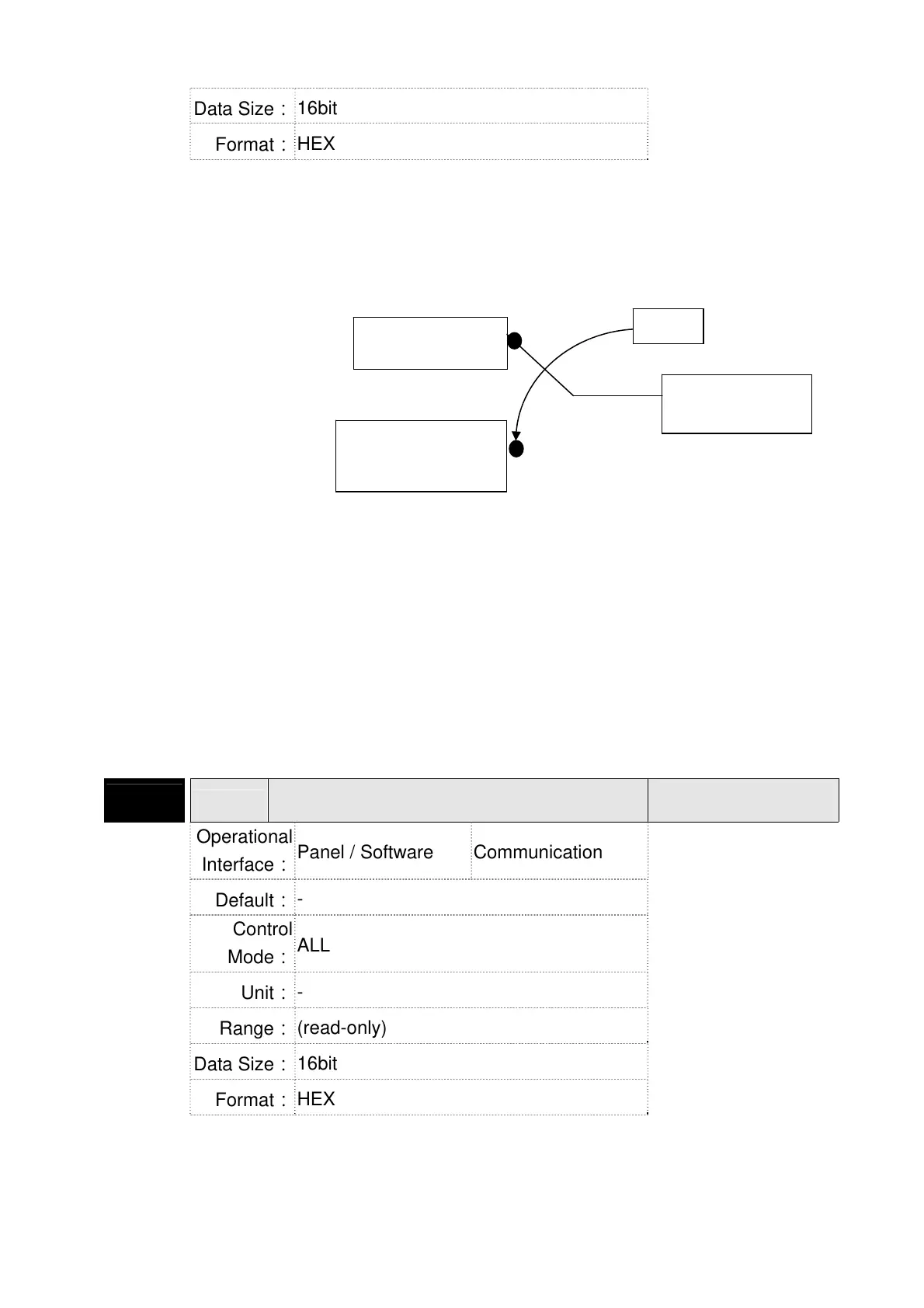
Settings:
The DI input signal can come from external terminal (DI1 ~ DI8;
EDI9 ~ EDI14) or software SDI1 ~ 14 (Bit 0 ~ 13 of corresponding
parameter P4-07) and is determined by P3-06. The
corresponding bit of P3-06 is 1, which means the source is
software SDI (P4-07). If the corresponding bit is 0, then the
source is hardware DI. See the following graph:
Read parameters: shows the DI status after combination
Write parameters: writes the software SDI status
For example:
The value of reading P4-07 is 0x0011, which means DI1 and DI5
is ON after combination.
The value of writing P4-07 is 0x0011, which means software SDI1
and SDI5 is ON.
Please refer to P2-10 ~ P2-17 for the function programe of digital
input pin DI (DI1~DI8) and P2-36 ~ P2-41 for extended DI (EDI9 ~
EDI14).
P4-08★
PKEY
Input Status of the Drive Keypad
(Read-only)
Address: 0410H
0411H
Operational
Interface:
Panel / Software Communication
Related Section: -
Default:
-
Control
Mode:
ALL
Unit:
-
Range:
(read-only)
Data Size:
16bit
Format:
HEX
Settings:
The aim is to check if the five Keys, MODE, UP, DOWN, SHIFT
and SET can work normally. This parameter is also used to check
if the Keys are all functional when producing servo drives.
Software DI,
SDI1~14 (P4-07 bit)
External DI: DI1~8
EDI9~14
DI after
combination
P3-06
 Loading...
