Chapter 9 Communication ASDA-A2R Series
Revision December, 2014
9-9
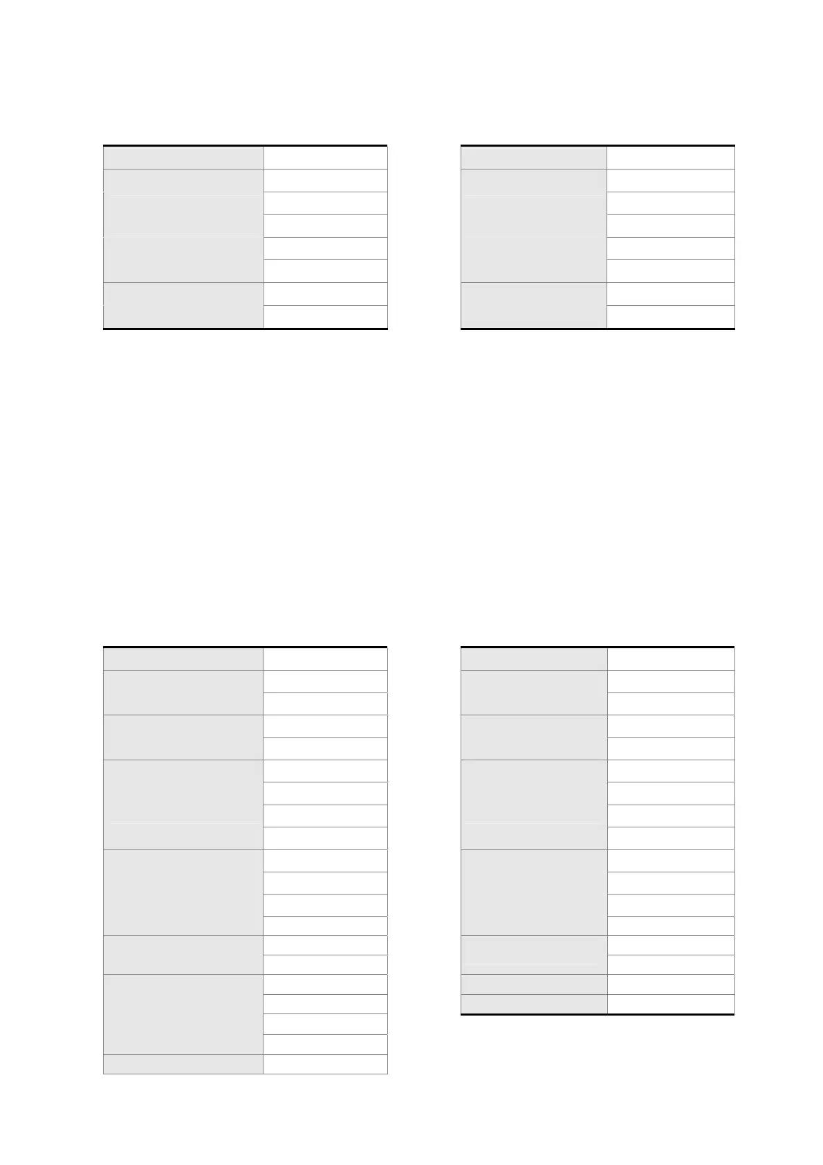
RTU mode:
Command message from the Master: Response message from the Slave:
Address 01H
Address 01H
Slave Function 06H Slave Function 06H
Starting data
address
02H (High word)
Starting data
address
02H (High word)
00H (Low word) 00H (Low word)
Data content
00H (High word)
Data content
00H (High word)
64H (Low word) 64H (Low word)
CRC Check Low 89H (Low word) CRC Check Low 89H (Low word)
CRC Check High 99H (High word) CRC Check High 99H (High word)
Note: Before and after the transmission in RTU mode, 10ms of silent interval is needed.
Example 3: function code 10H, write multiple words:
The Master issues command to the 1
st
Slave and writes 0BB8H and 0000H to the starting
address 0112H. That is to say, 0112H is written into 0BB8H and 0113H is written into 0000H.
The maximum allowable data in one single access is 10. The Slave sends the response
message to the Master after the writing is completed. The calculation of LRC and CRC will
be described in next chapter.
ASCII mode:
Command message from the Master: Response message from the Slave:
Start ‘:’ Start ‘:’
Slave Address
‘0’
Slave Address
‘0’
‘1’ ‘1’
Function
‘1’
Function
‘1’
‘0’ ‘0’
Starting data
address
‘0’
Starting data
address
‘0’
‘1’ ‘1'
‘1’ ‘1’
‘2’ ‘2’
Number of data
(In Word)
‘0’
Number of data
‘0’
‘0’ ‘0’
‘0’ ‘0’
‘2’ ‘2’
Number of data
(In Byte)
‘0’
LRC Check
‘D’
‘4’ ‘A’
The 1
st
data content
‘0’ End 1 (0DH)(CR)
‘B’ End 0 (0AH)(LF)
‘B’
‘8’
The 2
n
data content ‘0’
 Loading...
