Chapter 12 Setting of Motor Parameters ASDA-A2R Series
12-22 Revision December, 2014
STEP10: P1-74.U (The filter setting of CN5 linear scale) (digit in thousands)
When the feedback signal of CN5 connector is the AB type square wave from motor
encoder or the signal of linear scale, setup the proper digital filter can effectively suppress
the noise. Users can refer to the maximum approximate value of feedback pulse and setup
the buffer value of P1-74.U. The setting value of U and its corresponding filter frequency:
U = 1 (20Mhz)
U = 2 (10Mhz)
U = 3 (6.66Mhz)
U = 4 (1.66Mhz)
U = 5 (833Khz)
U = 6 (416Khz)
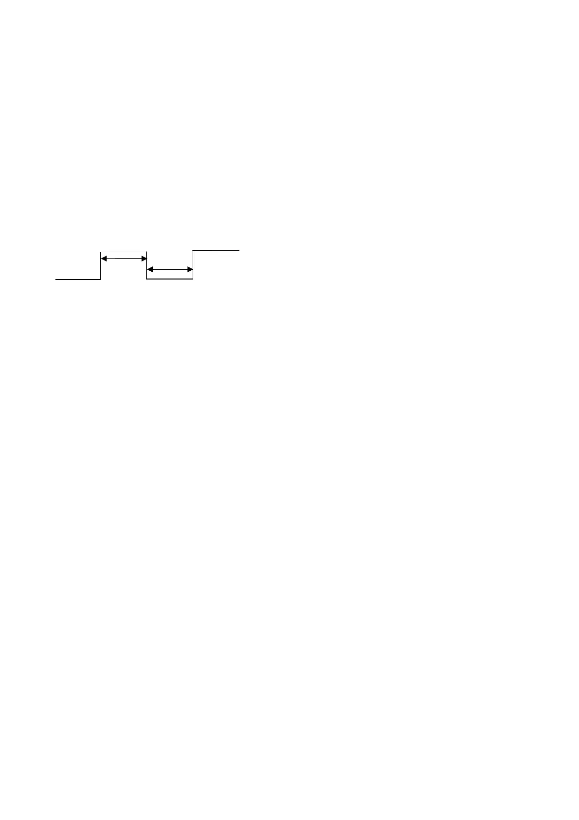
Take filter frequency 20MHz (50ns) as the example:
The single phase with the width smaller than 50ns will be filtered.
For example, when connecting to 1um of linear scale, the maximum speed of motor is 1m/s.
At the moment, the maximum moving frequency of linear scale is 1MHz (quardruple
frequency) and the minimum width of single phase pulse is 2us (= 500khz). Consider the
change of pulse width or the motor’s moving speed might exceed the upper limit, thus,
setup a buffer range (set U to 4).
STEP11: Output A/B pulse by pass from CN5: P1-74.Y (digit in tens)
When the feedback signal of CN5 connector is the AB type square wave from motor
encoder or the signal of linear scale, output A/B pulse by pass from CN5 in order to transmit
a more realistic signal to the controller. Set P1-74.Y to 1 will do.
50ns
50ns
 Loading...
