Chapter 15 CANopen Overview C2000 Plus
15-23
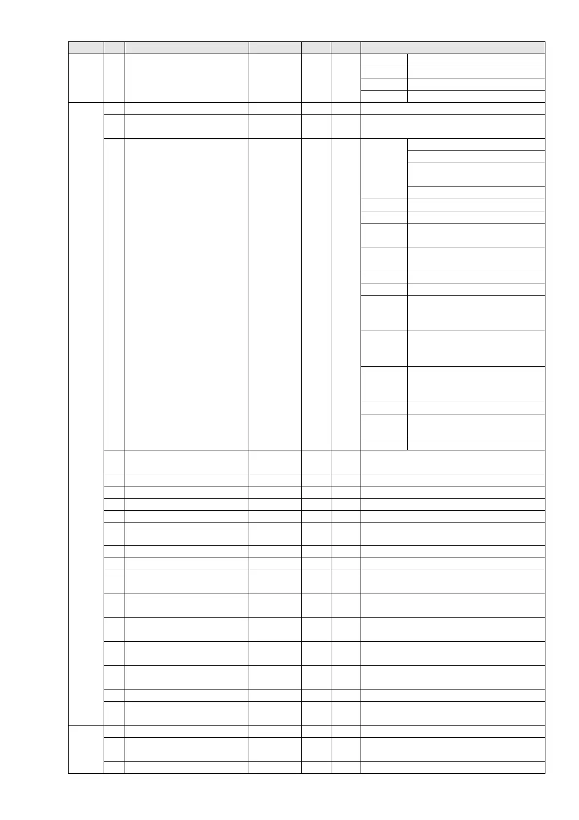
Index Sub Definition Default R/W Size Note
3 Other trigger 0 RW U16
bit0 1
: E.F. ON
bit1 1: Reset
bit2 1: Base Block (B.B) ON
bit15–3 Reserved
2021H 0 Number 10 R U8
1 Error code 0 R U16
High byte: Warning Code
Low byte: Error Code
2 AC motor drive status 0 R U16
bit1–0 00B
: stop
01B: decelerate to stop
10B: waiting for operation
command
11B: in operation
bit2 1: JOG command
bit4–3 00B: Run forward
01B: switch from run in reverse
to run forward
10B: switch from run forward
to run in reverse
11B: Run in reverse
bit7–5 Reserved
bit8 1: Master Frequency
command controlled by
communication interface
bit9 1: Master Frequency
command controlled by
analog signal input
bit10 1: Operation command
controlled by communication
interface
bit11 1: Parameter lock
bit12 1: Enable the digital keypad
copy parameter function
bit15–13
Reserved
3
Freq. command
(XXX.XXHz)
0 R U16
4 Output freq. (XXX.XXHz) 0 R U16
5 Output current (XX.XA) 0 R U16
6 DC bus voltage (XXX.XV) 0 R U16
7 Output voltage (XXX.XV) 0 R U16
8
The current step run by the
multi- step speed commend
0 R U16
9 Reserved 0 R U16
A Display counter value(c) 0 R U16
B
Display output power factor
angle (XX.X°)
0 R U16
C
Display output torque
(XXX.X%)
0 R U16
D
Display actual motor speed
(rpm)
0 R U16
E
Number of PG feedback
pulses (0–65535)
0 R U16
F
Number of PG2 pulse
commands (0–65535)
0 R U16
10 Power output (X.XXXkWh) 0 R U16
17
Multi-function display
(Pr.00-04)
0 R U16
2022H 0 Reserved 0 R U16
1
Display the drive’s output
current
0 R U16
2 Counter value 0 R U16