Chapter 15 CANopen Overview C2000 Plus
15-24
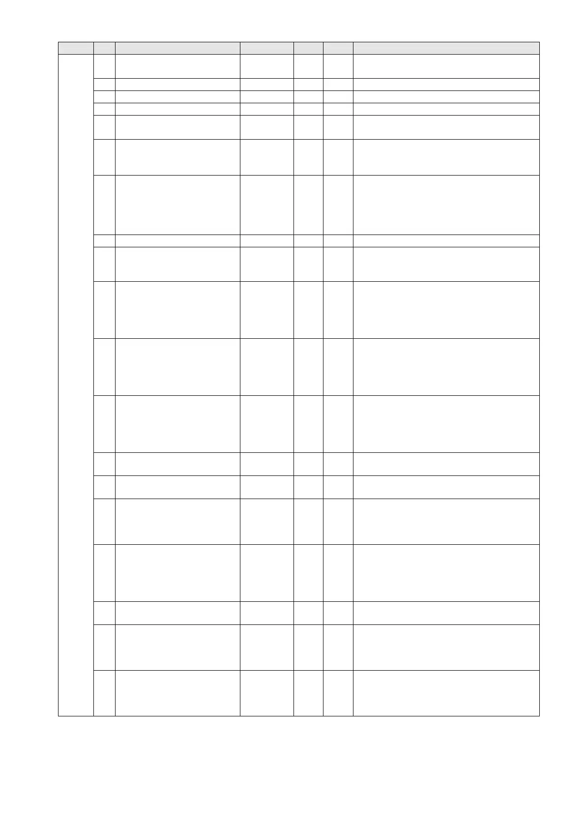
Index Sub Definition Default R/W Size Note
3
Actual output frequency
(XXX.XXHz)
0 R U16
4 DC bus voltage (XXX.XV) 0 R U16
5 Output voltage (XXX.XV) 0 R U16
6 Power factor angle (XX.X°) 0 R U16
7
Display the output power of
U, V, W in kW
0 R U16
8
Display the motor speed
estimated by the drive or
encoder feedback in rpm
0 R U16
9
Display the positive /
negative output torque
estimated by the drive
(+0.0: positive torque; -0.0:
negative torque)
0 R U16
A Display PG feedback 0 R U16
B
Display the PID feedback
value after enabling PID
function in %
0 R U16
C
Display the AVI analog
input terminal signal, 0–10
V corresponds to 0.00–
100.00% (see Explanation
2 in Pr.00-04)
0 R U16
D
Display the ACI analog
input terminal signal, 4–20
mA / 0–10 V corresponds to
0–100% (2.) (see
Explanation 2 in Pr.00-04)
0 R U16
E
Display the AUI analog
input terminal signal, -10–
10V corresponds to -100–
100% (see Explanation 2 in
Pr.00-04)
0 R U16
F
IGBT temperature of the
power module in
o
C
0 R U16
10
Display the temperature of
capacitance in
o
C
0 R U16
11
The digital input status (ON
/ OFF), refer to Pr.02-12
(see Explanation 3 in Pr.00-
04)
0 R U16
12
The digital output status
(ON / OFF), refer to Pr.02-
18
(see Explanation 4 in Pr.00-
04)
0 R U16
13
Current step for the multi-
step speed operation
0 R U16
14
The corresponding CPU
digital input pin status (d.)
(see Explanation 3 in Pr.00-
04)
0 R U16
15
The corresponding CPU
digital output pin status (O.)
(see Explanation 4 in Pr.00-
04 )
0 R U16