Chapter 2 InstallationC2000 Plus
2-7
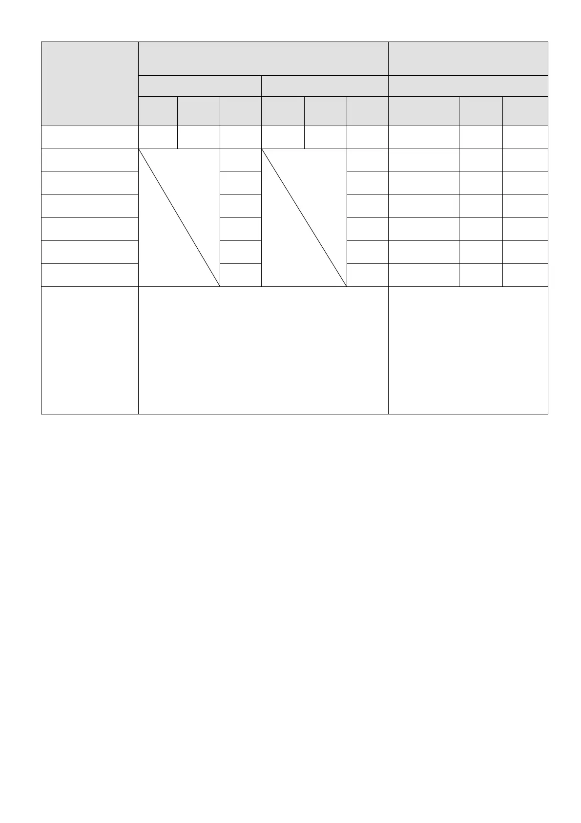
Model No.
Airflow Rate for Cooling
Power Dissipation for
AC Motor Drive
Flow Rate (Unit: cfm) Flow Rate (Unit: m
3
/ hr) Power Dissipation (Unit: watt)
External Internal Total External Internal Total
Loss External
(Heat sink)
Internal Total
VFD2000C63B-00
VFD2000C63B-21
248.1 135.3 383.4 421.6 229.9 651.4 3415.0 1585.0 5000.0
VFD2500C63B-00
VFD2500C63B-21
409.7
696.0 4751.7 1498.3 6250.0
VFD3150C63B-00
VFD3150C63B-21
409.7 696.0 5695.4 2179.6 7875.0
VFD4000C63B-00
VFD4000C63B-21
563.0 956.4 6796.2 3203.8 10000.0
VFD4500C63B-00
VFD4500C63B-21
952.9 1618.9 7313.6 3936.4 11250.0
VFD5600C63B-00
VFD5600C63B-21
952.9 1618.9 9553.4 4446.6 14000.0
VFD6300C63B-00
VFD6300C63B-21
952.9 1618.9 11042.4 4707.6 15750.0
The required airflow shown in the table is for
installing single drive in a confined space.
When installing multiple drives, the required air
volume should be the required air volume for single
drive X the number of the drives.
The heat dissipation shown in
the table is for installing single
drive in a confined space.
When installing multiple drives,
volume of heat dissipation
should be the heat dissipated
for single drive X the number of
the drives.
Heat dissipation for each model
is calculated by rated voltage,
current and default carrier.
Table 2-3