EasyManua.ls Logo

Delta C2000 Plus Series

Delta C2000 Plus Series
1259 pages
To Next Page IconTo Next Page
To Previous Page IconTo Previous Page
Loading...
Chapter 12 Descriptions of Parameter SettingsC2000 Plus
12.1-01-34
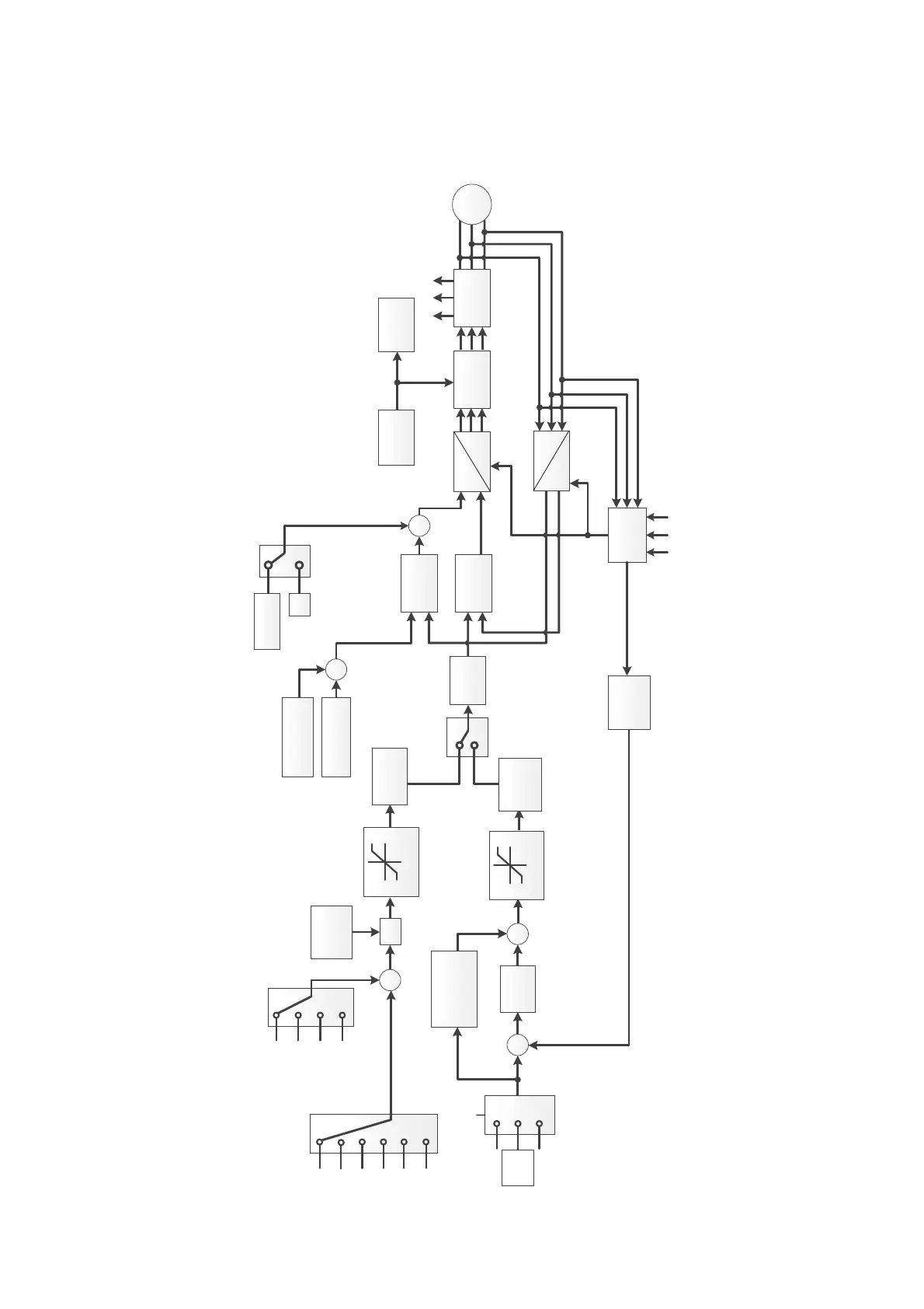
Pr.00-13 = 4, SynRM TQC Sensorless control diagram is as follows; refer to Section 12-2 for
SynRM auto-tuning procedure, follow those steps to adjust speed control mode, and then set
Pr.00-13 = 4 to be sensorless torque control.
U
a
U
b
U
c
IGBT
PWM
dq
abc
q axis
current
control
Pr01-01~01-02
Pr05-33~05-43
θ
e
d axis
current
control
dq
abc
Automatic
Voltage
Regulator
Pr07-23
I
q
*
I
d
*
Dcbus
dectection
Over
voltage
protection
SynRM
I
a
I
b
I
c
ω
r
θ
e
θ
e
Speed
estimate
轉矩
速度
Torque/Speed
switch
Torque cmd
low pass
filter
Pr11-35
ASR
-
+
Pr11-12
0
Pr11-33
Torque
command
Source
Pr11-34
3
4
5
RS485
Analog input
1
2
CANopen
Reserve
Communication
option card
+
Maximum
Torque
command
X
Pr11-27
Torque Limit
Pr06-12
Pr11-17~11-20
Pr06-12
Pr11-17~11-20
++
Pr11-00 Bit0=0
set Pr11-06~11-11
Pr11-00 Bit0=1
set Pr11-03~11-05
+
Pr
11
-
28
Source of
Torque offset
0
Pr11-29
Analog input
Pr11-30~Pr11-32
0
1
2
3
0
1
Pr11-36
Speed Limit
Pr11-37&Pr11-38
2
Pr11-37
Pr11-38
Pr00-20
Source of Frequency
Pr00-20
T
q
*
q軸電流
計算
Torque
offset
Gain of ASR
speed
feedforward
ASR Low
pass filter
time
Pr11-14
Pr10-55
Pr10-56
U
a
U
b
U
c
Estimated
Speed low
pass filter
Pr10-34
High Freq.
Injection
Pr10-51
Pr10-52
Pr10-39
+
0
+
Field weakening
MTPA
Pr10-31
Pr10-35
Pr10-36
+
+
Torque Limit

Table of Contents

Related product manuals