Chapter 12 Description of Parameter SettingsC2000 Plus
12.2-30
Load operation adjustment and steady state adjustment at constant speed
11. Load operation test
B1. Low-frequency carrier capacity test (the output frequency is < 20% of rated speed):
a. If the frequency switch from I/F mode to PM Sensorless is zero (Pr.10-39 = 0 Hz),
increase Pr.10-54 (magnetic flux linkage estimate low-speed gain).
b. If the output frequency is less than Pr.10-39 (frequency to switch from I/F mode to
PM Sensorless), increase Pr.10-31 (I/F mode, current command).
B2. Carrier capacity test during acceleration
In heavy load operation, accelerate the motor to rated speed according to the
acceleration time:
a. If the motor responds too slowly or an over current occurs during the acceleration,
increase Pr.10-57 (Ki phase-locked loop).
12. Steady state test at constant speed, check if the motor operates stably at constant speed.
a. If the motor’s output frequency presents periodic low-frequency wave, increase
Pr.10-34 (PM sensorless speed estimator low-pass filter gain), or adjust the ASR
parameters.
b. If the motor’s output frequency presents extreme vibration, decrease Pr.10-34 (PM
sensorless speed estimator low-pass filter gain) or Pr.10-56 (Kp phase-locked loop).
PM Sensorless adjustment parameters
Refer to Section 12-1 “Description of Parameter Settings” for detailed information.
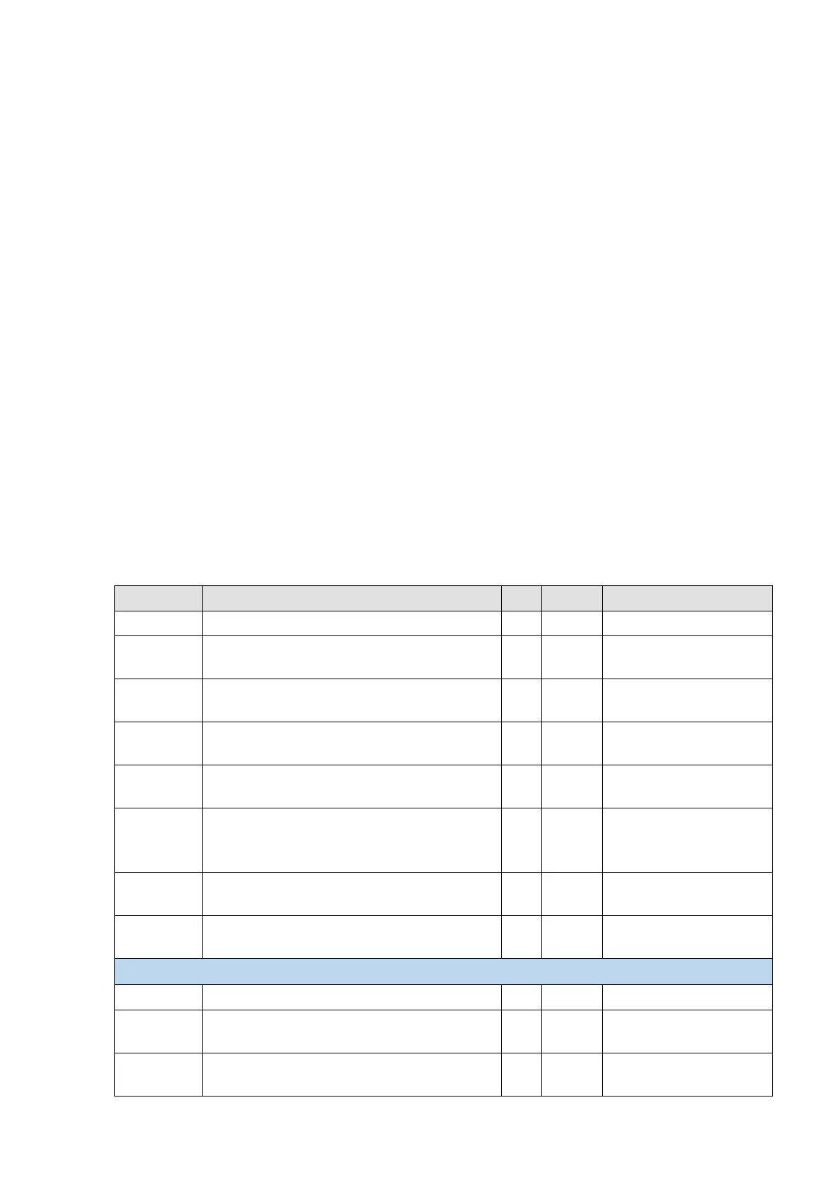
Parameter Description Unit Default Settings
Pr.10-31
I/F mode, current command
% 40 150
Pr.10-34
PM sensorless speed estimator low-pass
filter gain
NA 1.00 0.00–655.35
Pr.10-39
Frequency to switch from I/F mode to PM
sensorless mode
Hz 20.0 0.0–599.0
Pr.10-40
Frequency to switch from PM sensorless
mode to I/F mode
Hz 20.0 0.0–599.0
Pr.10-54
Magnetic flux linkage estimate low-speed gain
(applied to 230V / 460V models)
% 100 10–1000
Pr.10-55
Magnetic flux linkage estimate high-speed
gain
(applied to 230V / 460V models)
% 100 10–1000
Pr.10-56
Kp of phase-locked loop
(applied to 230V / 460V models)
% 100 10–1000
Pr.10-57
Ki of phase-locked loop
(applied to 230V / 460V models)
% 100 10–1000
Initial Angle Estimating Parameters
Pr.10-42
Initial angle detection pulse value
NA 0.5 0.0–3.0
Pr.10-51
Injection frequency
(applicable when Pr.10-53 = 2)
Hz 500 0–1200
Pr.10-52
Injection magnitude
(applicable when Pr.10-53 = 2)
V
15.0 /
30.0
0.0–200.0
 Loading...


