Chapter 5 Main Circuit TerminalsC2000 Plus
5-6
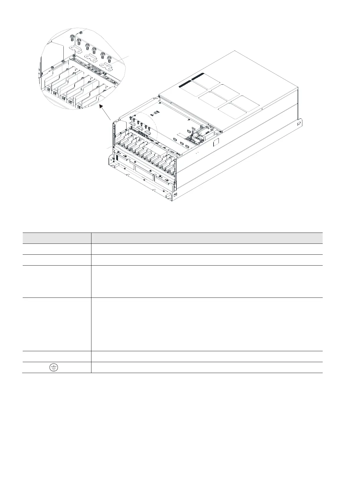
Figure 5-9
Terminals Descriptions
R/L1, S/L2, T/L3 Mains input terminals (three-phase)
U/T1, V/T2, W/T3 AC motor drive output terminals for connecting three-phase induction motor
+1/DC+, +2/DC+
Applicable to frame A–C
Connections for DC reactor to improve the power factor. Remove the jumper
before installing a DC reactor.
+1/DC+, -/DC-
Connections for brake module (VFDB series)
(for 230V models: ≤ 22 kW, built-in brake module)
(for 460V models: ≤ 30 kW, built-in brake module)
(for 690V models: ≤ 37 kW, built-in brake module)
Common DC bus
B1, B2 Connections for brake resistor (optional). Refer to Section 7-1 for details.
Ground connection; comply with local regulations.
Table 5-1
Tighten the screw after the short circuit plate is removed.
Screw torque: 100–110 kg-cm / (86.8–95.5 lb-in.) / (9.8–10.8 Nm)
Detail A
See
Detail A