Chapter 5 Main Circuit TerminalsC2000 Plus
5-11
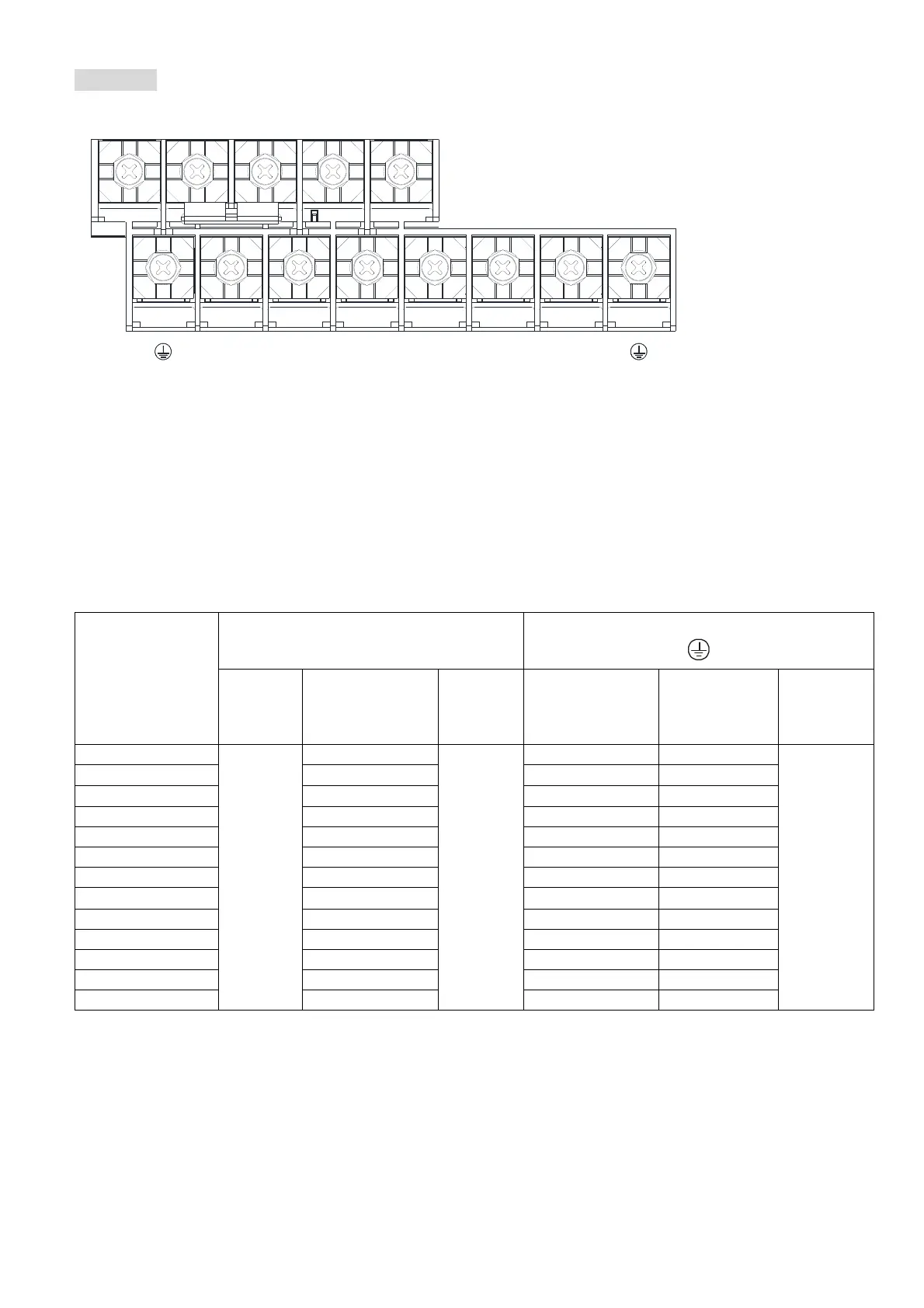
Frame C
U/T1
+2/DC+
R/L1 V/T2
-/DC- +1/DC+
S/L2 W/T3
B1 B2
T/L3
If you install at Ta 50°C environment, use copper wires that have a voltage rating of 600V and are
temperature resistance to 75°C or 90°C.
If you install at Ta 50°C above environment, use copper wires that have a voltage rating of 600V and
are temperature resistance to 90°C or above.
For VFD220C23A-21 models: if you insall at Ta 40°C above environment, use copper wires have a
voltage rating of 600V and are temperature resistance to 90°C or above.
To be UL installation compliant, you must use copper wires when installing. The wire gauge is based
on temperature resistance of 75°C, in accordance with UL requirements and recommendations. Do
not reduce the wire gauge when using high-temperature resistant wire.
+2/DC+ and +1/DC+: with 90 kg-cm / (78.2 lb-in) / (8.83 Nm) (±10%) torque
Model Name
Main Circuit Terminals
R/L1、S/L2、T/L3、U/T1、V/T2、W/T3、
-/DC-、+1/DC+、+2/DC+、B1、B2
Terminal
Max. Wire
Gauge
Min. Wire Gauge
Screw
Spec. and
Torque
(±10%)
Max. Wire Gauge
Min. Wire
Gauge
Screw Spec.
and Torque
(±10%)
VFD150C23A-21
50 mm
2
(1/0 AWG)
50 mm
2
(1 AWG)
M8
80 kg-cm
(69.4 lb-in.)
(7.84 Nm)
50 mm
2
(1 AWG) 25 mm
2
(4 AWG)
M8
80 kg-cm
(69.4 lb-in.)
(7.84 Nm)
VFD185C23A-21
50 mm
2
(1/0 AWG)
50 mm
2
(1/0 AWG)
25 mm
2
(4 AWG)
VFD220C23A-21
50 mm
2
(1/0 AWG)
50 mm
2
(1/0 AWG)
25 mm
2
(4 AWG)
VFD185C43A-21 25 mm
2
(4 AWG) 25 mm
2
(4 AWG) 16 mm
2
(6 AWG)
VFD220C43A-21
25 mm
2
(4 AWG) 25 mm
2
(4 AWG) 16 mm
2
(6 AWG)
VFD300C43A-21 35 mm
2
(2 AWG)
35 mm
2
(2 AWG) 16 mm
2
(6 AWG)
VFD185C4EA-21 25 mm
2
(4 AWG) 25 mm
2
(4 AWG)
16 mm
2
(6 AWG)
VFD220C4EA-21 25 mm
2
(4 AWG) 25 mm
2
(4 AWG) 16 mm
2
(6 AWG)
VFD300C4EA-21 35 mm
2
(2 AWG)
35 mm
2
(2 AWG) 16 mm
2
(6 AWG)
VFD185C63B-21 10 mm
2
(8 AWG) 10 mm
2
(8 AWG) 10 mm
2
(8 AWG)
VFD220C63B-21 16 mm
2
(6 AWG) 16 mm
2
(6 AWG) 16 mm
2
(6 AWG)
VFD300C63B-21 25 mm
2
(4 AWG) 25 mm
2
(4 AWG) 16 mm
2
(6 AWG)
VFD370C63B-21 35 mm
2
(2 AWG) 35 mm
2
(2 AWG) 16 mm
2
(6 AWG)