Chapter 12 Description of Parameter SettingsCP2000
12.1-12-12
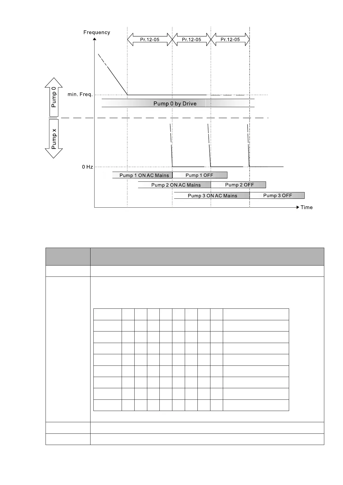
Diagram 12-11: Sequence of switching motors at Fixed Quantity Control with PID
– Decreasing Demand
Parameter setting:
Parameter
Setting
Description
Pr.12-00=3 Choose Fixed Quantity Control
Pr.12-01=X
Number of Motors: maximum of eight motors. After you set the number of connected
motors, the multi-function output terminals automatically follow the setting as shown in the
table below.
Pr.12-01 01 02 03 04 05 06 07 08
Pr.02-13 55 55 55 55 55 55 55 55 Motor 1 by Mains
Pr.02-14 56 56 56 56 56 56 56 Motor 2 by Mains
Pr.02-15 57 57 57 57 57 57 Motor 3 by Mains
Pr.02-36 58 58 58 58 58 Motor 4 by Mains
Pr.02-37 59 59 59 59 Motor 5 by Mains
Pr.02-38 60 60 60 Motor 6 by Mains
Pr.02-39 61 61 Motor 7 by Mains
Pr.02-40 62 Motor 8 by Mains
Table 2: Setting of Multi-function Output Terminal on Circulating Motors
Pr.12-05=X Delay time for Fixed Quantity Circulation at Motor Switching (seconds)
Pr.12-06=X Frequency for switching motors at Fixed Quantity Circulation (Hz)
 Loading...


