6 Installation
Installation and Operation Manual for Inverter RPI M50A_12s V1 EU EN 2017-03-09
62
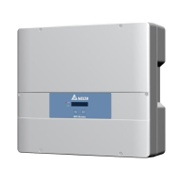
6.5.5 Connecting digital inputs and external
power-off (EPO)
Pin assignments
Pin Designa-
tion
Sort-circuit Assigned action
1 V1 – –
2 K0 V1 + K0
External power-off
(EPO)
3 K1 V1 + K1
Set maximum active power
to 0%
4 K2 V1 + K2
Set maximum active power
to 30%
5 K3 V1 + K3
Set maximum active power
to 60%
6 K4 V1 + K4
Set maximum active power
to 100%
7 K5 V1 + K5 Reserved
8 K6 V1 + K6 Reserved
After commissioning, the relays can be defined as make-contact
or break-contact for the external shutdown on the display “8.4.8
EPO (External power-off )”, page 101.
Wiring examples
Fig. 6.20: Connection example 7: Connecting an external
power-off
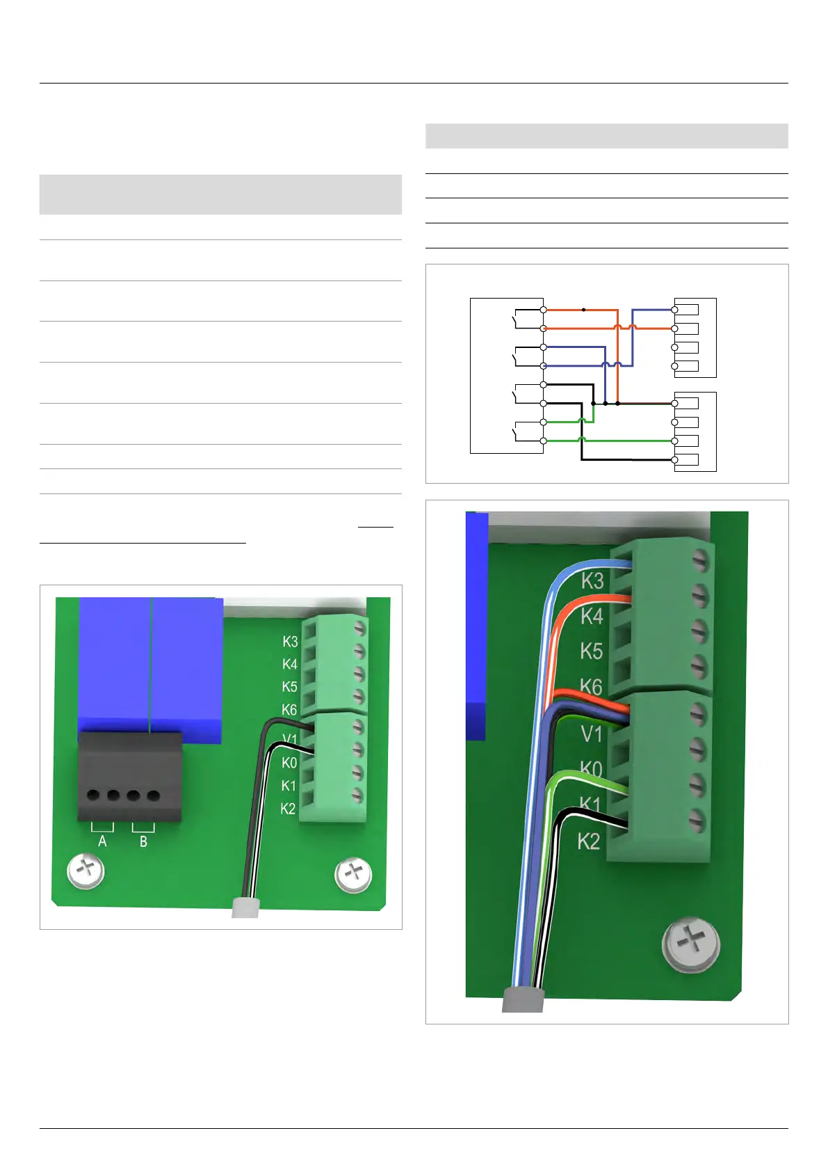
Connecting a ripple control receiver
Power limiting to: Short circuit
0% Terminals V1 and K1
30% Terminals V1 and K2
60% Terminals V1 and K3
100% Terminals V1 and K4
K3
K4
K5
K6
V1
K0
K1
K2
R 4
R 3
R 2
R 1
Digital inputsRipple control receiver
Fig. 6.21: Connection example 8: Connecting a ripple control
receiver

 Loading...