19
Chapter 3 Operation Panel
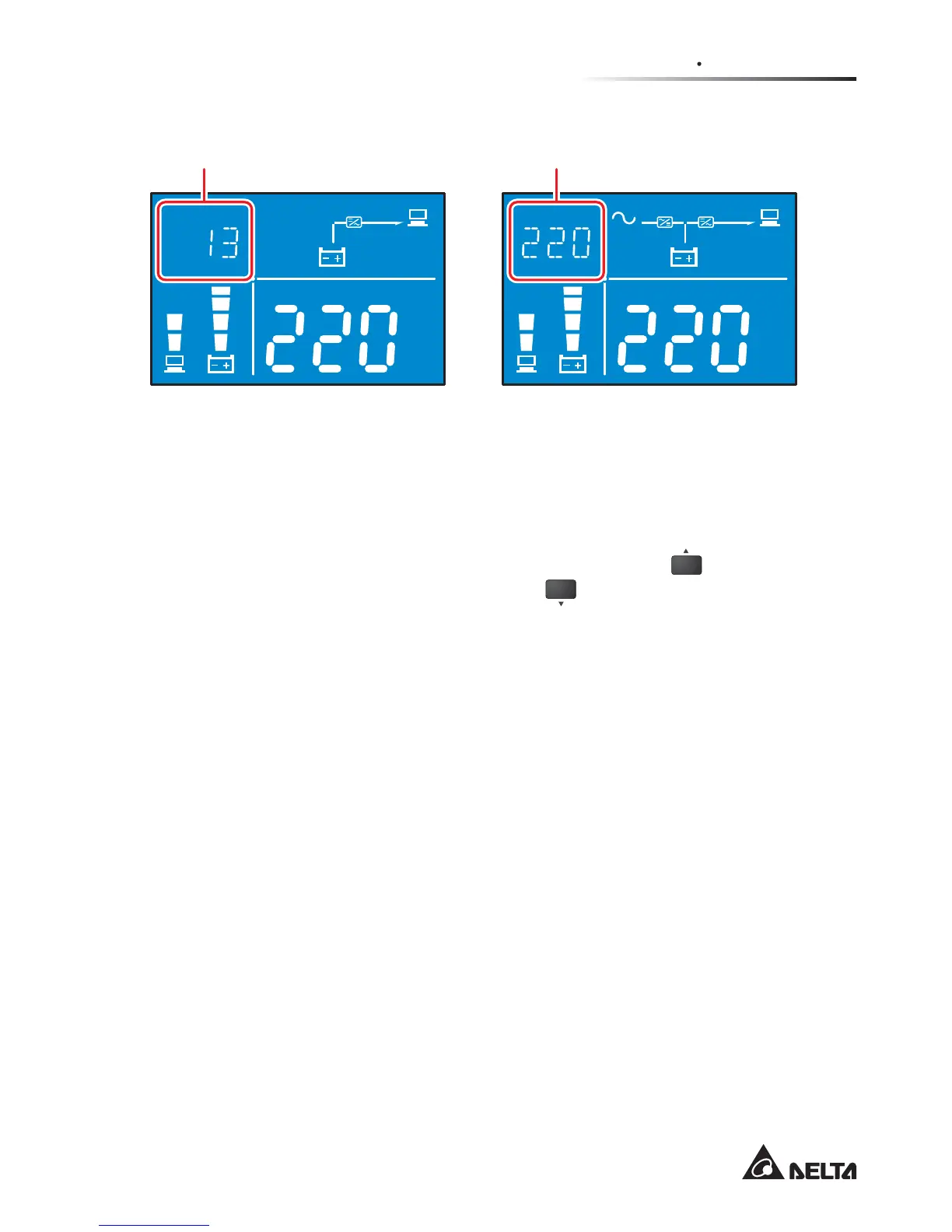
)LJXUHVHJPHQW'LVSOD\LQ%DWWHU\0RGHLQ$Q\2WKHU0RGH
Hz
KW
KVA
AH
MIN
MIN
ECO
V
V
%
IN
SET IN OUT BATT
RUN TIME
°C
LOAD TEST
Hz
KW
KVA
AH
MIN
MIN
ECO
V
V
%
IN
SET IN OUT BATT
RUN TIME
°C
LOAD TEST
In battery mode, here displays
the remaining battery time.
In any mode (except battery mode),
here displays the input voltage.
3.7 LCD Display Flow Chart
7KHIROORZLQJÀRZFKDUWKHOSV\RXWRXQGHUVWDQGKRZWRJRWKURXJKHDFKGLVSOD\
screen. Here, we take ‘Bypass Mode’ as an example. Press the
ON
button for 0.1
second to view the previous screen and press the
OFF
button for 0.1 second to view
the next screen.
Any No., diagram, icon, text, etc. shown in the LCD diagrams presented below are
for reference only. Actual display depends on the operation of the UPS.