I
NOTE
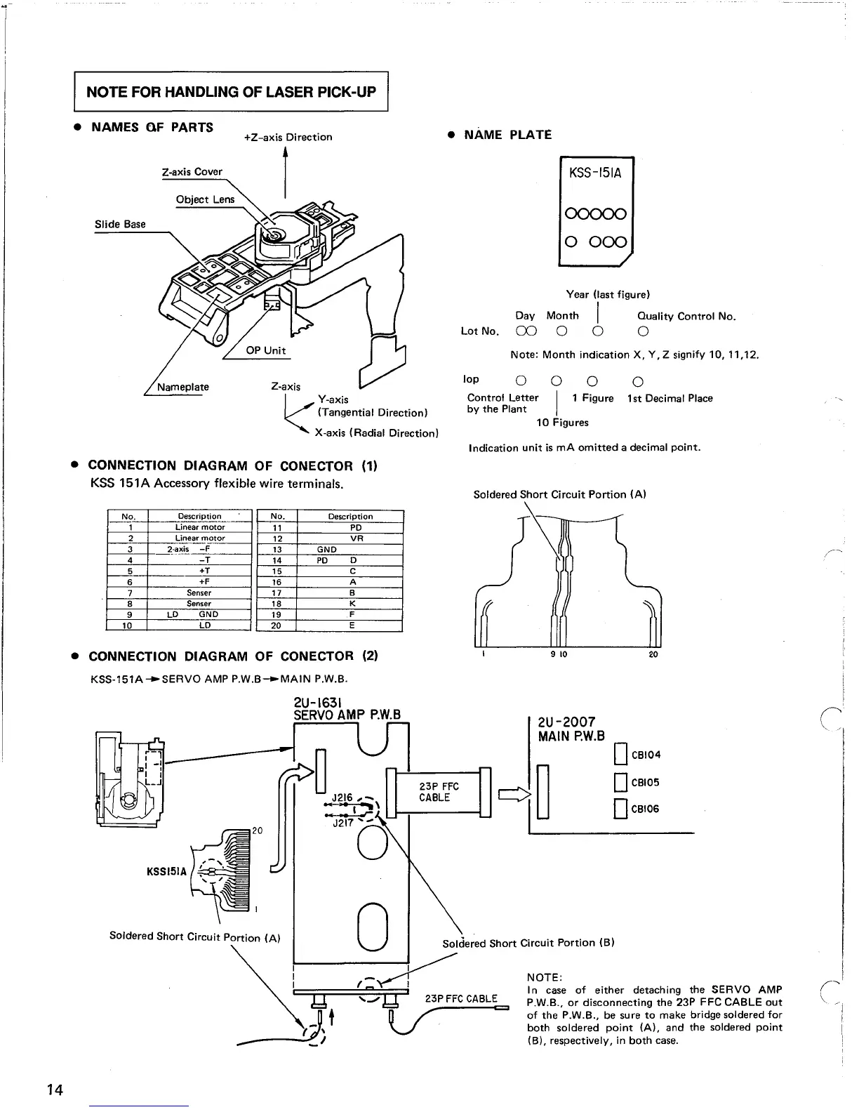
FOR HANDLING OF LASER PICK-UP
• NAMES OF PARTS
+Z-axis Direction
• NAME PLATE
KSS-15IA
Note:
Month
indication
X, Y, Z signify 10, 11,12.
0ססoo
0000
o
1st
Decimal Place
o 0
I 1 Figure
lop
0
Control Letter
by
the
Plant
10
Figures
Year (last figure)
Day
Month
I Quality Control No.
Lot No.
00
0 0 0
Z-axis
1/
Y-axis
~
(Tangential Direction)
X-axis (Radial Direction)
Z-axis Cover
Nameplate
Slide Base
Indication
unit
is
mA
omitted
a decimal
point.
20
• CONNECTION DIAGRAM
OF
CONECTOR (1)
KSS
151A
Accessory flexible wire terminals.
No.
Description
__
~
No.
Description
1
Linear
motor
11
PO
2
Linear
motor
12
VR
3
2_~~~.is
-F
13
GNO
4
-T
14
PO
0
5
+T
15
C
6
+F
16
A
7
Senser
17
B
8
Senser
18 K
9
LO
GNO
19
F
10
LO
20
E
• CONNECTION DIAGRAM OF CONECTOR (2)
Soldered
Short
Circuit
Portion
(A)
\
KSS-151A--SERVO
AMP
PW.B---MAIN
P.W.B.
2U-2007
MAIN
P.W.S
DCBI04
c=:::::1'-----n
__
0
CBIO_5
~
DC8IO'
20
2U-1631
SERVO
AMP
P.W.S
---~
~
UJ1--!-------I23P
FFC
J216
,,-
CABLE
...
°
1
-"
~
J2170
KSSI51A
Sol".""
Short
CI""I'
Portloo
IA) 0
SoI';'re"
Short
Ci,,""
Portloo
IB)
~
I
_~
NOTE:
lIn
I In case
of
either
detaching
the
SERVO
AMP
;g
'-QI
23P.
FFC
CABLE
PW.B.,
or
disconnecting
the
23P
FFC CABLE
out
Dt
if
~
of
the
P.W.B., be sure
to
make bridge soldered for
77\
V·
both
soldered
point
(A),
and
the
soldered
point
~----""-;..J
(B), respectively, in
both
case.
14