EasyManua.ls Logo

Denon DCD-3560 Service Manual

Denon DCD-3560
46 pages
To Next Page IconTo Next Page
Page #1 background imageLoading...
Page #1 background image
JS$
DEN
Hi-Fi
Component
SERVICE
MANUAL
STEREO CD PLAYER
MODEL
DCD-3560
i
I)
I
I
I:]
I
TABLE
OF
CONTENTS
OPERATING INSTRUCTIONS 2 - 13
NOTE FOR HANDLING OF LASER PiCK-UP
14,15
DISASSEMBLY 0
•••••••••••
0
•••••••••••••••••••••••••••••••••••••••••••••••••••
16,17
MECHANISM UNIT ADJUSTMENT 18
ADJUSTMENT
0
•••••••••••••
0
••
000
••••••••••••••••••••••••••••••••••••••••••••••••••
19 - 26
Ie
TERMINAL FUNCTION LIST
26
-
31
PARTS LIST OF P.W.BOARD 0
••••••••••••••••••••••••••••••••••••••••••••••
32 - 35
PARTS LIST OF EXPLODED VIEW
0 0
•••••••••••••••••••••••••
:
••••••••••••••••••••••••••
36
EXPLODED VIEW
0
•••••••••••••••••••••••••••••••••••••••••••••••••••••••••••••••••••••
.'
37
EXPLODED VIEW OF FG-621 MECHANISM UNIT
0
••••
38
PARTS LIST OF FG-621 MECHANISM UNIT 38
PoW.BOARD
.0.0
•••••••••
0
••••••••
o' 0
•••
0
•••••••••••••••••••••••••••••••••
0
•••••••••
39-41
WIRING DIAGRAM 0
•••••••••••••••••••••••
0
••••••••••••
0
•••••
42
SEMICONDUCTORS
0
•••••••••••••••••••••••••••••••••••
0
•••••
0
•••••
43,
44
SCHEMATIC DIAGRAM 0 0 0 0
•••••••••
0
•••••••••••••••••••••••
0 0
•••••
0 0
•••••••••
45, 46
NIPPON
COLUMBIA
CO
..
LTD.

Table of Contents

Question and Answer IconNeed help?

Do you have a question about the Denon DCD-3560 and is the answer not in the manual?

Denon DCD-3560 Specifications

General IconGeneral
TypeCD Player
Dynamic range100dB
Channel separation110dB
Digital outputscoaxial, optical
Disc formatCD
Frequency Response2Hz - 20kHz
Line output2.0V

Summary

Safety and Handling Precautions

General Safety Warnings

Essential safety guidelines to prevent fire or shock hazards.

Model-Specific Labels

Identification and meaning of labels for U.S.A. models.

British Model Wiring Information

Wiring color code details specific to British models.

Product Features and Design

Advanced Audio Technologies

Highlights features like Super Linear Converter, digital filter, and audio outputs.

Operational Design and Functions

Covers simple design, quick search, linear motor, and remote control.

Component Identification and Functions

Control Panel Overview

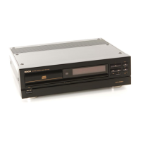
Identifies and explains power switch, disc holder, display, and search buttons.

Playback and Navigation Controls

Details playback buttons, time/display functions, and output controls.

Ports and Terminals

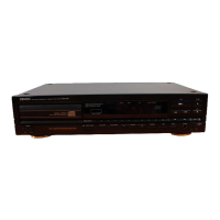
Describes various output terminals, headphone jack, and switches.

Initial Setup and Connections

Preparation Before Operation

Steps for removing shipping restraints and preparing the player.

Audio and Digital Connections

Guides for connecting variable, fixed, balanced audio, and digital outputs.

Connection Safety Precautions

Important guidelines for safe and correct equipment connections.

Playback Modes and Operations

Disc Handling and Loading

Steps for opening, closing, and loading discs.

Normal CD Playback

How to start, stop, and play a standard CD.

Advanced Playback Features

Explains direct search, programming, time search, auto space, repeat, and pause functions.

Special Playback and Timer Functions

Timer-Controlled Playback

Instructions for setting and using the timer playback feature.

Disc Care and Remote Operation

Compact Disc Handling and Storage

Guidelines for proper care, cleaning, and storage of discs.

Remote Control Unit Usage

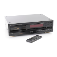
Instructions for operating the remote, including battery installation and usage cautions.

Advanced Playback Functions

Track Selection and Auto Edit

Details track number selection, direct search, and the auto edit function.

Troubleshooting and Specifications

Common Operational Issues

Solutions for problems with disc holder, sound, and playback.

Technical Specifications Overview

Lists key technical details of the CD player's performance and features.

Laser Pick-up Handling and Care

Laser Pick-up Handling Precautions

Critical safety and care instructions for the laser pick-up unit.

Laser Diode Safety and Deterioration

Guidelines on laser diode safety, handling, and identifying deterioration.

Disassembly Procedures

External Panel Removal

Steps to remove top, side, and front panels.

Internal Assembly Removal

Instructions for removing housing assembly and laser pick-up.

Mechanism Unit Adjustments

Turntable Height Calibration

Steps to adjust turntable height using a spacer.

Spindle Motor Calibration

Guides for adjusting the spindle motor using test equipment.

Service Adjustment Procedures

Service Mode Entry and Functions

How to start the service program and understand button functions.

Potentiometer Calibration

Locating and setting initial values for adjustment potentiometers.

PLL, Slide, and Tracking Adjustments

Procedures for calibrating PLL, slide offset, and tracking.

Focus Gain and Offset Calibration

Steps for adjusting focus gain and offset.

Tracking Gain and Offset Verification

Procedures to adjust and check tracking gain and offset.

Special Modes and IC Functions

Heat Run Mode Operation

Instructions for activating and using the heat run mode.

CXA1081S IC Terminal Functions

Detailed explanation of CXA1081S IC terminal functions.

Additional IC Terminal Functions

CXA1082AS/1182S IC Terminal Details

Explains terminal functions for CXA1082AS/1182S ICs.

Integrated Circuit Block Diagrams

CXA IC Block Diagrams

Visual representation of CXA1082AS/1182S IC internal structure.

CXD1125Q IC Block Diagram

Diagram illustrating functional blocks of the CXD1125Q IC.

CXD1125Q IC Terminal Functions

CXD1125Q Terminal Details

Explains the function of each terminal for the CXD1125Q IC.

Parts Lists

P.W.B. Component Lists

Lists parts for 2U-2007 Servo/Sig. Unit.

Servo Amp and Display Unit Parts

Lists components for 2U-1631 Servo Amp and 2U-1688 Display Unit.

Audio Unit Component List

Lists parts for the 2U-2008 Audio Unit.

Power Supply and Motor Drive Parts

Lists components for power supply and motor drive units.

Parts List Notes and Ordering

Explains symbols, warnings, and how to order parts.

Exploded Views and Accessories

Exploded View Parts Identification

Lists parts referenced in exploded view diagrams.

Packing and Accessory List

Details packing materials and included accessories.

Exploded View Diagram

CD Player Assembly Diagram

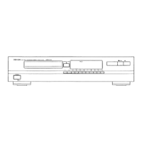
Illustrates the physical layout and assembly of the CD player.

FG-621 Mechanism Unit Details

FG-621 Mechanism Exploded View

Visual breakdown of the FG-621 mechanism's assembly.

FG-621 Mechanism Parts List

Comprehensive list of parts for the FG-621 mechanism.

Printed Wiring Board Schematics

2U-2008 Audio Unit P.W.B. Schematic

Detailed schematic for the 2U-2008 audio unit.

2U-2007 Servo & Sig. Unit P.W.B. Schematic

Schematic for the 2U-2007 servo and signal unit.

Other Unit P.W.B. Schematics

Schematics for display, power supply, servo amp, and motor drive units.

System Wiring Diagram

Overall Unit Interconnections

Illustrates how all major units and components are interconnected.

Semiconductor Component Details

Integrated Circuit (IC) Diagrams

Pinout diagrams and basic schematics for various ICs.

Transistor and Diode Pinouts

Diagrams showing pin configurations for transistors and diodes.

Related product manuals