I
I
L)
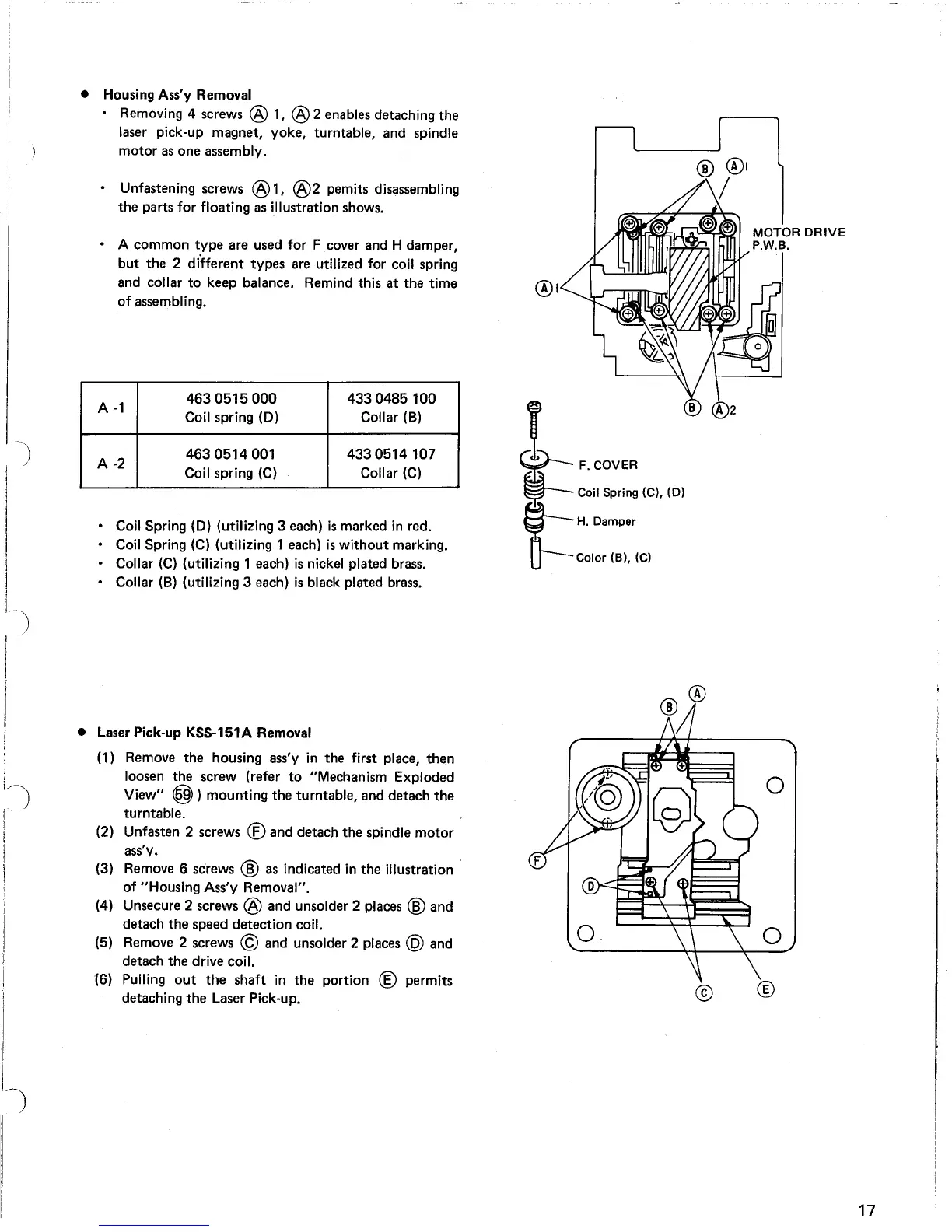
• Housing Ass'y Removal
• Removing 4 screws
® 1, ®2 enables detaching
the
laser pick-up magnet, yoke, turntable, and spindle
motor
as
one assembly.
• Unfastening screws @ 1,
@2
pemits disassembling
the
parts for floating as illustration shows.
• A common
type
are used for F cover and H damper,
but
the 2 different types are utilized for coil spring
and collar
to
keep balance. Remind this
at
the
time
of
assembling.
A
-1
4630515000
4330485100
Coil spring
(0)
Collar (8)
A
-2
4630514001
4330514107
Coil spring
(C)
Collar
(C)
• Coil Spring
(0)
(utilizing 3 each)
is
marked
in
red.
• Coil Spring
(C)
(utilizing 1 each)
is
without
marking.
• Collar
(C)
(utilizing 1 each)
is
nickel plated brass.
• Collar (8) (utilizing 3 each)
is
black plated brass.
t=
;:1~:'~":
,eJ.
'0'
~H.Damper
0--
Color
(B), (C)
MOTOR
DRIVE
P.W.B.
• Laser Pick-up KSS-151A Removal
(1) Remove
the
housing ass'y
in
the first place, then
loosen
the
screw (refer
to
"Mechanism Exploded
View"
@)
mounting
the
turntable, and detach
the
turntable.
(2) Unfasten 2 screws
® and detach
the
spindle
motor
ass'y.
(3) Remove 6 screws
® as indicated
in
the illustration
of
"Housing Ass'y Removal",
(4) Unsecure 2 screws
@ and unsolder 2 places ® and
detach
the
speed detection coil.
(5) Remove 2 screws
© and unsolder 2 places @ and
detach
the
drive coil.
(6) Pulling
out
the
shaft
in
the
portion ® permits
detaching
the
Laser Pick-up.
17