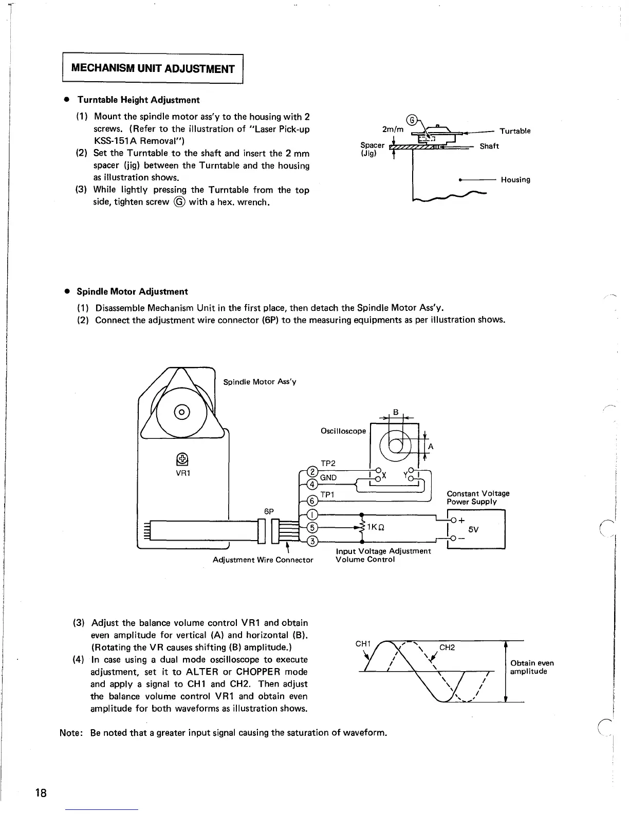
MECHANISM UNIT ADJUSTMENT
----
Housing
Shaft
c:::;;~===?---
Turtable
Spacer
$ZZ¢:2::;aIlEi~=;
(Jig)
• Turntable Height
Adjustment
(1) Mount
the
spindle
motor
ass'y
to
the housing with 2
screws. (Refer
to
the
illustration of "Laser Pick-up
KSS-151 A Removal")
(2)
Set
the
Turntable
to
the
shaft and insert the 2 mm
spacer
(jig)
between
the
Turntable and
the
housing
as
illustration shows.
(3) While lightly pressing
the
Turntable from
the
top
side, tighten screw @ with a hex. wrench.
• Spindle Motor
Adjustment
(1) Disassemble Mechanism Unit
in
the first place,
then
detach
the
Spindle Motor Ass'y.
(2) Connect
the
adjustment
wire connector (6P)
to
the measuring equipments
as
per illustration shows.
Constant
Voltage
Power
Supply
Input
Voltage
Adjustment
Volume
Control
B
""mo~op,
~A
I X Y I
, I
Spindle
Motor
Ass'y
Adjustment
Wire
Connector
@
VR1
(3) Adjust
the
balance volume control VR1 and obtain
even amplitude for vertical
(A)
and horizontal (B).
(Rotating
the
VR causes shifting
(B)
amplitude.)
(4)
In
case using a dual mode oscilloscope
to
execute
adjustment,
set
it
to
ALTER
or
CHOPPER mode
and apply a signal
to
CH
1 and CH2. Then adjust
the
balance volume control VR1 and obtain even
amplitude for
both
waveforms as illustration shows.
Obtain
even
amplitude
Note:
Be
noted
that
a greater
input
signal causing
the
saturation
of
waveform.
18