Chapter 2
Hardware Options and Installation
XL™ Series Hardware Options and Installation 2-1
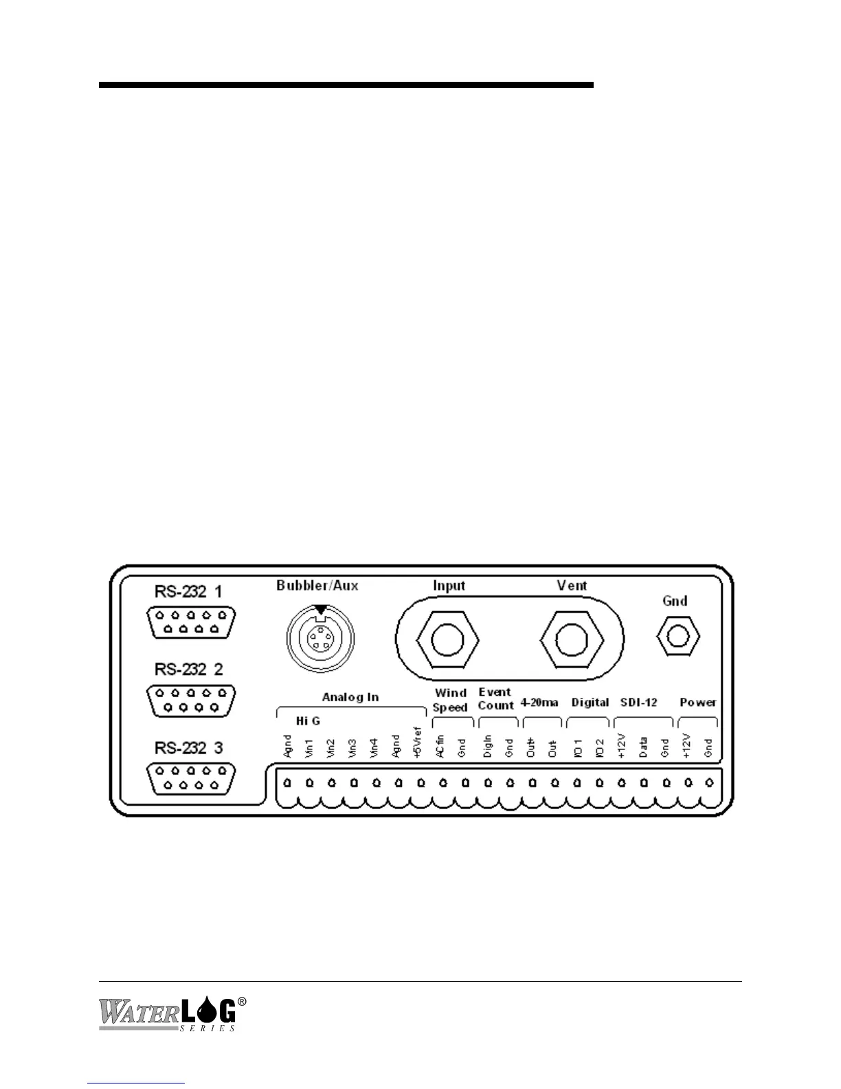
Figure 2-1A Models H-350XL™/H-500XL™/H-510XL™ Front Panel Description
2.1 Mechanical Mounting
In this manual, referring to the XL is the same as referring to any of the XL Series data logger /
DCP’s. This chapter describes the basic procedure for installing the XL™. This includes all
wiring and plumbing. For proper installation you will need:
"The XL™ mounting hardware
"Two open end wrenches (7/16", 9/16")(Model H-350XL™ Only)
"Small flat blade screw driver
"Power and communication cables
"The XL™ Series Owner’s Manual
2.2 Front Panel Description
Figure 2-1A shows the wiring panel and illustrates the physical input and output features of the
XL™ Series models H-350XL™, H-500XL™ and the H-510XL™ and briefly describes their
purposes. Figure 2-1B shows the same wiring panel but for the H-522 and the H-522Plus. These
diagrams will help show where you should make connections to your XL™ Series data logger /
DCP.
 Loading...