Chapter 19
Alarm Call Out
XL™ Series Alarm Call Out 19-1
19.1 Overview
The alarm call out options were added for NIWA in New Zealand but may be useful to other
users also. The overall intent was to allow a method for the unit to call out to another computer
system using a few different modes such as modems and radios.
The following menus are used to enable and define what data will be sent based on alarm
conditions. The data is sent via a modem or RF radios using a very specific format. Up to ten
data values can be monitored and sent based on user entered alarm conditions.
19.2 Alarm Call Out Menus
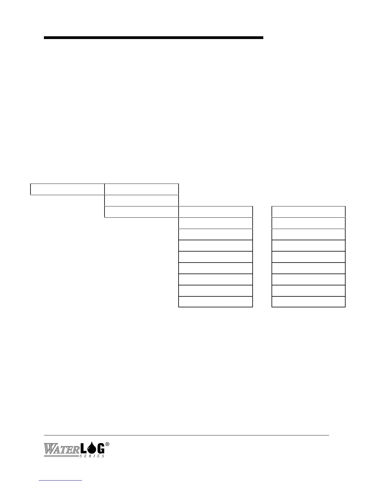
Built in Menu Structure: Alarm Call Out Screens.
Alarm Setup -> Alarms Enabled [No ]
Alarm Retries [0]
Individual Setup -> Source 1 [None ]-> ... Source 10 [None ]
Trg 1 [Always ]-> ... Trg 10 [Always ]
Set Pnt 1[1.00 ]-> ... Set Pnt10[1.00 ]
Rst Pnt 1[1.00 ]-> ... Rst Pnt10[1.00 ]
Tx Tag 1 [Alarm1]-> ... Tx Tag 10 [AlarmX]
S# 1[0 ]-> S#10[0 ]
Comm 1 [Direct ]-> ... Comm 10 [Direct ]
Ph# 1[N/A ]-> ... Ph#10[N/A ]
Force Alarm 1? ... Force Alarm 10?