2-12 Hardware Options and Installation XL™ Series
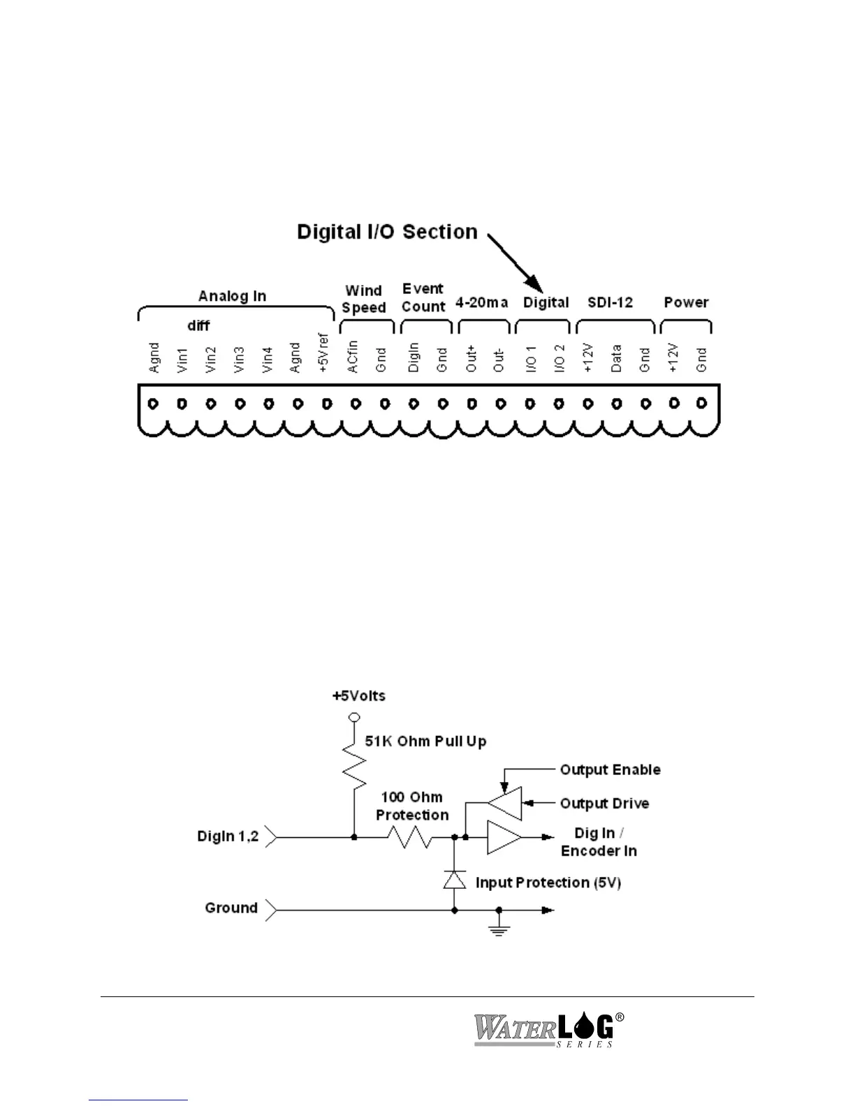
Figure 2-12 Digital I/O Section
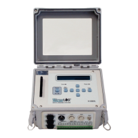
Figure 2-13 Basic Digital I/O Schematic
2.2.12 Digital I/O 1 and 2
Pins 14 and 15 of the terminal block provide connection points for the two digital I/O signals.
Notice there is no specific ground point for these signals. Use the digital ground pin of the event
counter or the SDI-12 ground. Do not use the analog grounds.
The two digital I/O signals can be configured independently as inputs or as outputs. In the input
mode, the signal has an internal pull up resistor of 51K Ohms. This allows a switch closure to
ground to activate the input. It can also be driven using normal logic levels. As an output, the
drive capability is limited by a 100 Ohm protection resistor. The output will still be about 4.0
volts with a 10.0 mA or less load. When both pins are configured as inputs, they may be used as
a quadrature shaft encoder input. The two digital signals can also be used to simulate a
quadrature shaft encoder. Figure 2-13 shows a simplified schematic of how these pins are
configured.