2-4 Hardware Options and Installation XL™ Series
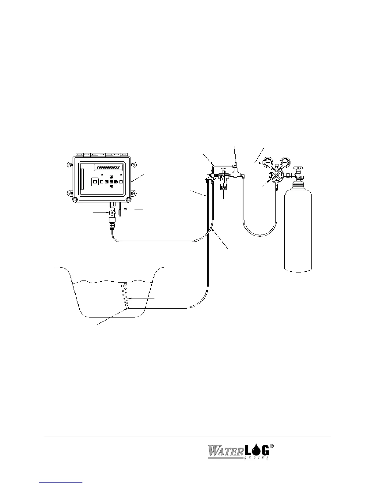
Figure 2-2 Conoflow Gas Purge Stream Gauge Installation
DIFFERENTIAL
REGULATOR
PRESSURE
RELIEF VALVE
POWER
30 BUBBLES
PER MINUTE
SITE-FEED
GAS PURGE
LINE ORIFICE
GAS PRESSURE
TO MANOMETER
H-350XL™
20 - 30 PSI
MOUNT
ON WALL
FEEDBACK TUBE
NITROGEN
SUPPLY
CYLINDER
REGULATOR
TO RIVER
2.2.3.1 Sample Installation for the Conoflow System (H-350XL only)
Figure 2-2 shows a typical H-350XL™ installation for water depth measurement using the
Conoflow gas purge system. To install the H-350XL™, secure it to the wall of the instrument
shelter or bench top using the provided mounting hardware. This will prevent it from moving or
shifting and pulling on the wires and tubing connected to other equipment. The H-350XL™
should be mounted so moisture and dust will not settle on the main I/O panel. Normally
vertically is the best with the main I/O panel facing down and the display keypad facing out.
 Loading...