6-6 Serial Port Options XL™ Series
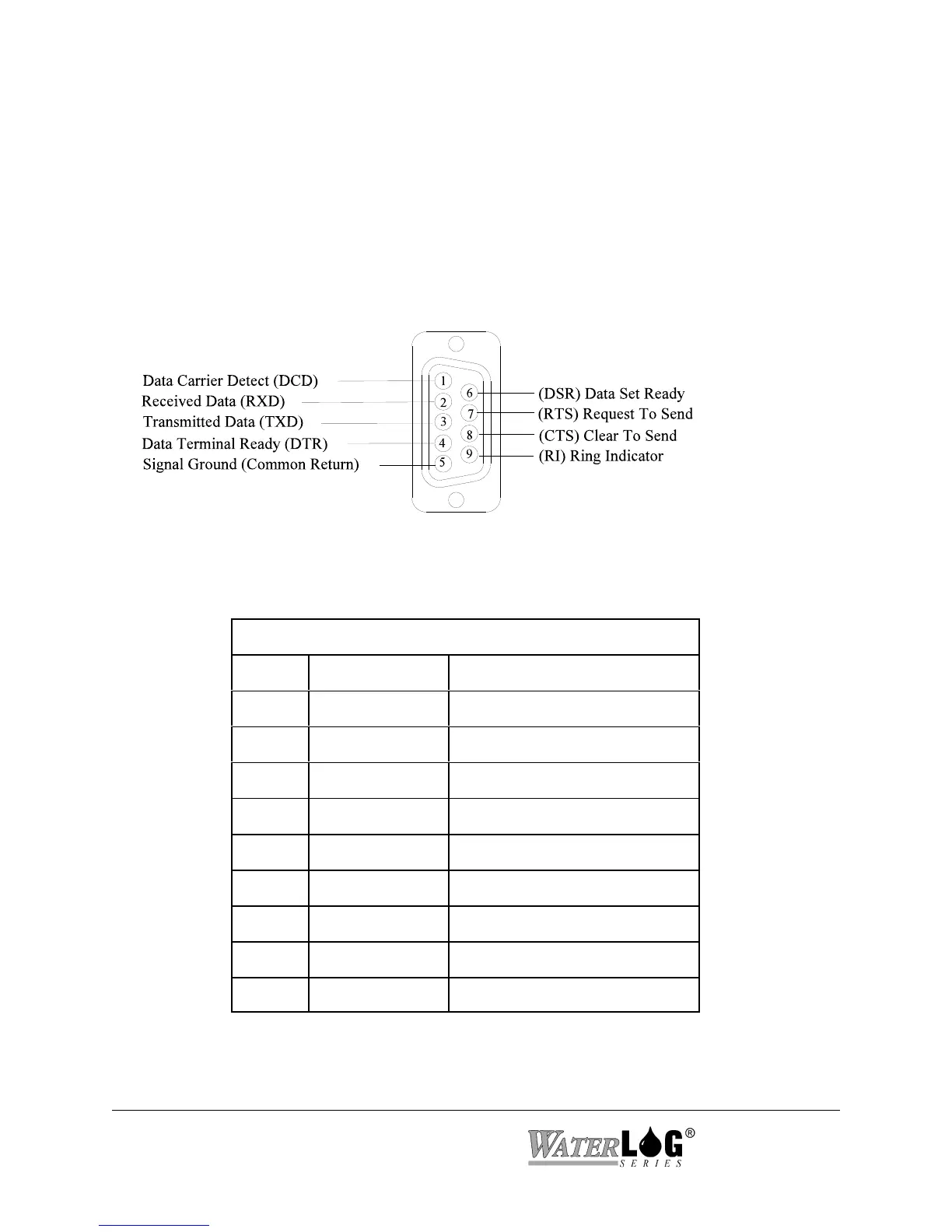
Figure 2-5 RS-232 Connector
6.3 Serial Port Hardware Description
The three RS-232 ports are used to connect to a PC, GOES Transmitter, modem, remote display,
or other serial equipment for standard serial communications. These ports are configured as a
DTE type of device. This means they will plug directly into a modem (a DCE type device), but
will require a NULL modem adaptor if connected to a PC (a DTE type device). The NULL
modem cable crosses the communication lines allowing two similar devices to communicate.
Figure 2-5 shows the pin out for all three ports.
SERIAL PORT PIN-OUT
PIN DIRECTION NAME
1 Input Data Carrier Detect (DCD)
2 Input Receive Data (RD)
3 Output Transmit Data (TD)
4 Output Data Terminal Ready (DTR)
5 Ground (GND)
6 Input Data Set Ready (DSR)
7 Output Request To Send (RTS)
8 Input Clear To Send (CTS)
9 Input Ring Indicator (RI)
6.4 Serial Port Functions
 Loading...