2-14 Hardware Options and Installation XL™ Series
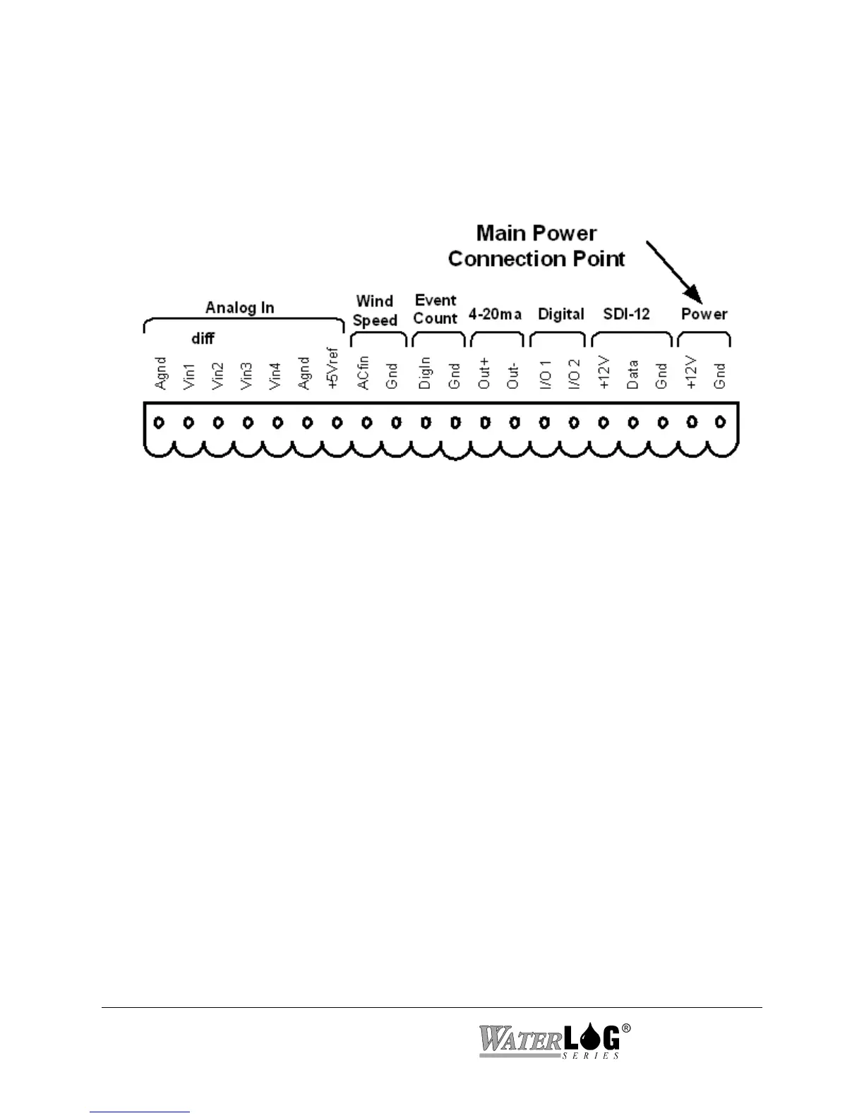
Figure 2-16 Main Power Connection Point
2.2.14 Power Connections
The last two pins at the far right of the terminal block provide the main connection points for
system power and ground.
Note: When connecting to or removing the wires from these connection points, it is important
to remove the terminal block from the XL™ first, or to have the other end of the wires
disconnected from the battery. This helps prevent loose wires with live voltages
accidently come in contact with other I/O connection points.
2.3 Testing the Installation
After hooking up the battery, the Power light should begin flashing every 5 to 10 seconds. This
indicates that the battery is providing 10 volts or more to the XL™. Press the display On/Off
button and the display should come on, indicating the instrument is functional and ready to use.
You will find detailed user setup information and menu options that will allow complete test and
verification of all sensor connections and operation in the next two chapters.
 Loading...