27
LT-2329
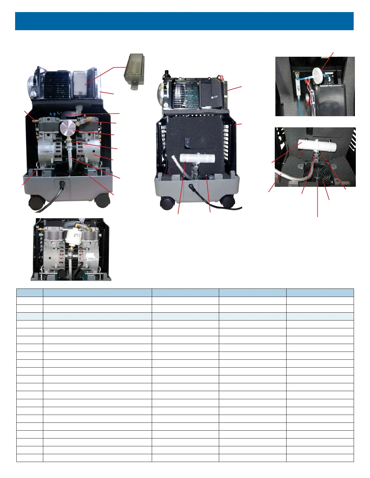
FIGURES, DIAGRAMS AND PARTS LIST
PART DESCRIPTION
1025DS 1025KS 1025UK
1 Accumulator Tank 1025D-610 1025D-610 1025D-610
2 Auxiliary Oxygen Port 525DD-635 525DD-635 525DD-635
Cabinet Parts:
3 Base 1025D-603 1025K-603 1025K-603
4 Compressor Box w/ Foam 1025D-615 1025D-615 1025D-615
5 Filter Door 525DD-639 525DD-639 525DD-639
6 Front Cover 525DD-611 525DD-611 525DD-611
7 Rear Cover 525DD-612 525DD-612 525DD-612
8A Cabinet Screw (Machine) 525DD-628 525DD-628 525DD-628
8B Cabinet Screw (Thread-forming) 525DD-636 525DD-636 525DD-636
9 Cable Tie (Large) 505DZ-617 505DZ-617 505DZ-617
10 Capacitor (Motor Start/Run) 1025DS-616 1025KS-616 1025UK-616
11 Caster, Non-locking 501DZ-603 501DZ-603 501DZ-603
12 Bed Check Valve PVO2D-607 PVO2D-607 PVO2D-607
13 Circuit Breaker 1025D-613 1025K-613 1025K-613
14 Cooling Fan 1025D-634 1025D-634 1025D-634
15 Cooling Fan Guard N/A N/A N/A
16 Compressor 1025D-625 1025K-625 1025K-625
17 Compressor Mounting Plate Package 1025D-632 1025D-632 1025D-632
18 Compressor Rebuild Kit 1025D-643 1025K-643 1025K-643
19 Exhaust Mufer 1025D-705 1025D-705 1025D-705
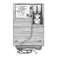
Rear Inside - Compressor Removed
1025 Unit with Auxiliary Oxygen Port
Behind Front Cover
23
19
10
14, 15
4
Rear Inside
21
22
27
16, 18 (not
shown)
34
30
29
43
17
10 (Location of
capacitor on
model 1025DS)
32
Inside Compressor Box
Exhaust
Muffler
Exhaust
Hose from
Rotary Valve
Heat
Exchange
Tube
Cooling Fan
& Guard
Rotary
Valve
10
(Location of capacitor on
models 1025KS and 1025UK)
Old style compressor
filter and connections
(no longer used)