LT-2329
22
COMPONENT TESTING, REPAIR AND REPLACMENT
4. Carefully place compressor in compressor box so that motor mount threads
are protruding through the holes in the base of the unit.
5. Lean unit backwards slightly and reinstall motor mount nuts.
NOTE– Ensure the compressor mounting and retaining plates are positioned
properly to prevent excessive noise and vibration.
6. Reconnect intake hose beneath intake lter.
7. Rotate heat exchange tube to the left 90°.
8. Install compressor lter by attaching tubing and ladder clamps to
compressor exhaust tting and heat exchange tube. Ensure heat exchange
tube is not touching mounting plate or fan guard.
9. Reconnect compressor electrical connector.
COOLING FAN
The cooling fan provides a constant air ow to cool the compressor. The cooling
fan is located in the bottom of the unit below the compressor.
A defective cooling fan may cause the compressor’s internal thermo-protective
(thermal cut off) device to activate and shut the compressor off. Should this
condition occur, the compressor will require several minutes for the thermo-
protective device to reset.
If the cooling fan is defective, it must be
replaced:
1. Make sure the unit is unplugged from the wall outlet.
2. Use the Cabinet Removal instructions listed previously to open the unit.
3. Use the To Remove the Compressor instructions listed under Compressor.
4. Disconnect the cooling fan connector from the PC board.
5. Note the position of the fan, wires and fan guard before removing the four
retaining screws that secure the fan to the base of the unit.
6. Remove the defective fan and secure the replacement fan in position with
the four retaining screws.
NOTE– When installing the fan, be sure the air ow directional arrow on the
side of the fan is directed away from the compressor and fan guard is reinstalled
properly.
7. Reconnect the electrical connector.
8. Reinstall the compressor.
FLOW METER
The DeVilbiss 1025 series oxygen concentrator ow meter (1025D-607) has an
operating ow rate of 2-10 LPM. Flows below 2 LPM may cause the low ow
alarm to activate.
NOTE– Do not use a low output ow meter.
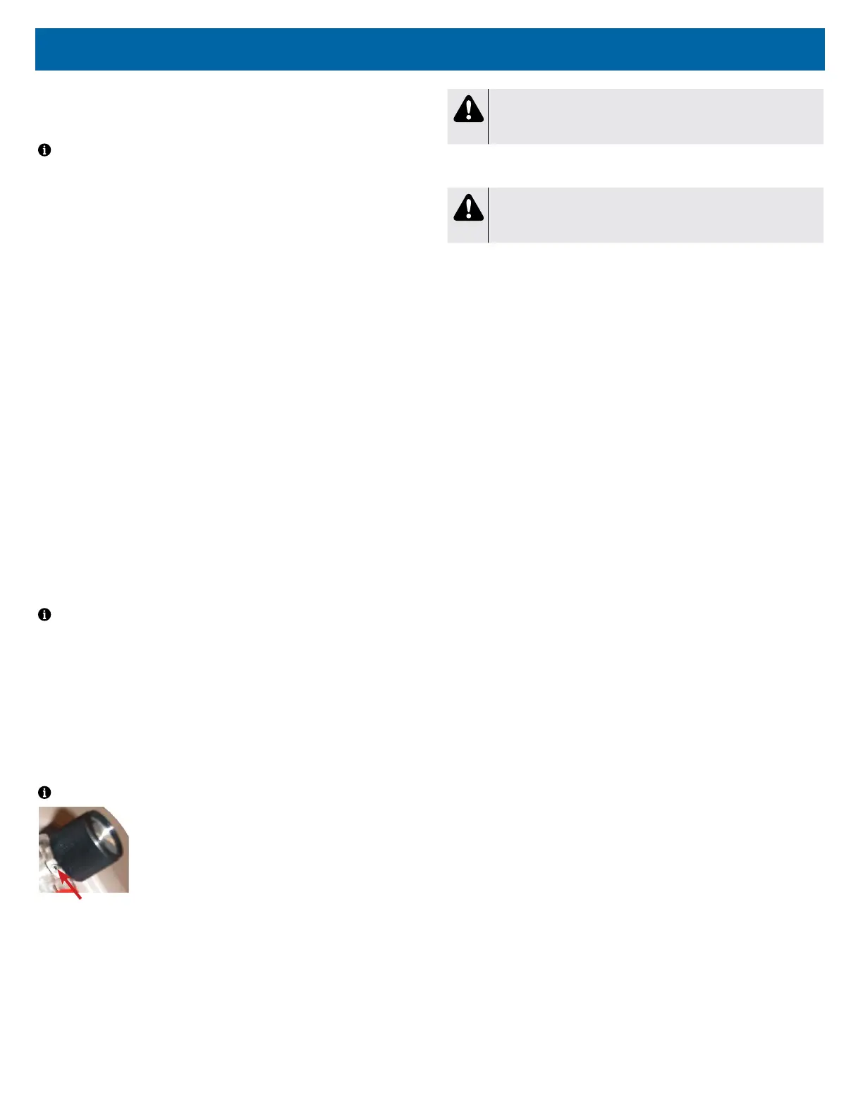
Locking Screw
The ow meter is pressure compensated and has an
accuracy level of ±5% of full scale at all liter ows except at
10 LPM. Accuracy at 10LPM is +0% / -5%. The ow meter
can be locked using a 1/16th inch Allen wrench and
tightening the locking screw behind the ow meter knob.
To check for leaks in the flow meter tubing:
1. Check for leaks using a certied leak detection solution such as Snoop® or
equivalent (must not contain ethylene glycol).
2. Apply leak test solution to all ttings and hose connections with the unit
running.
CAUTION
Do not apply leak test solution to any part of the rotary valve or the
main PC Board assembly.
3. I f an air leak is present, the solution will bubble. All leaks should be repaired
before putting the concentrator back in service.
WARNING
Electric Shock Hazard. Use caution when leak testing near electrical
connections.
To replace the flow meter:
1. Make sure the unit is unplugged from the wall outlet.
2. Use the Cabinet Removal instructions listed previously to open the unit.
3. From behind the front cabinet, remove the 2 hoses from the ow meter.
4. Unscrew both the top and bottom ow meter ttings and remove the ow
meter by pushing it out through the front cabinet.
5. Install new ow meter and reconnect hoses.
HOUR METER
The digital hour meter can be seen on the status indicator panel and is mounted
directly onto the PC board. If the hour meter malfunctions, the PC board will
need to be replaced.
Refer to PC board replacement instructions on page 24.
MANIFOLD
The manifold is attached to the accumulator tank and performs the same function
as a purge harness. It directs a small amount of pressurized oxygen into the
discharging sieve bed to aid the nitrogen exhaust process while it ensures that
the majority of pressurized oxygen is directed into the accumulator tank. The
manifold also prevents reverse ow of oxygen from the accumulator to the sieve
beds.
See CHECK VALVES: MANIFOLD and SIEVE in this manual for additional
information.