21
LT-2329
COMPONENT TESTING, REPAIR AND REPLACMENT
To inspect and/or replace internal
components:
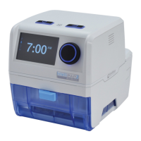
1. Place compressor upright and remove the eight screws that hold the
compressor heads in place. When removing the heads, be sure to keep
each head and its components with the correct compressor side.
2. Check for proper placement of or damage to the gaskets on the bottom of
the compressor heads. Replace if damaged.
Valve Plate
Reed Valve
Reed Valve
Screw
Head Gaskets
Retainers
3. Remove reed valve plates. A reed valve is located on each side of the valve
plate.
4. The compressor reed valves should be ush with the valve plate. If the
valve is broken or not ush with the valve plate, or foreign matter is
detected inside the head, clean or replace the compressor reed valves.
To replace the compressor reed valves:
a. Remove the screw holding the compressor reed valves in position on
the valve plate and discard the used reed valves.
b. Position the new reed valves so that they are centered and completely
cover the holes in the valve plate.
c. Place the metal retainers on the reed valves and secure with the reed
valve screw.
5. Check for proper placement of or damage to the rubber o-ring on the
bottom of the valve plate. Replace if damaged. Refer to the compressor
rebuild kit pictures on page 19.
6. Remove piston sleeves by pulling upward and inspect cup seal on pistons.
Replace if badly worn or damaged.
Sleeve
Cup Seal
Retainer
Plate
Cup Seal
Piston
Screws
To replace cup seal:
a. Remove both rod screws from top of piston. Note the position of the
screws since they are different lengths.
b. Remove the cup retainer plate.
c. Discard defective cup seal.
d. Place new cup seal into position.
e. Replace cup retainer plate.
f. Secure with screws.
7. Clean inside surface of sleeves before reinstalling. Position sleeve at 45
degree angle over the piston. Carefully push it down as you rotate it slightly
around the top of the piston until it is in place.
8. Place valve plates on the compressor so that heads of reed valve screws
are aligned with the indentation in top of pistons.
9. Install the compressor heads so that the holes in the heads are aligned with
the holes in the compressor housing.
10. Secure compressor heads with the screws.
To replace the compressor:
CAUTION
The 1025DS concentrators use a GSE compressor with a 60 mfd
capacitor. The 1025KS/1025UK concentrators use a GSE
compressor with a 17.5/15 mfd capacitor, respectively. If replacement
is necessary, be sure the correct capacitor is installed.
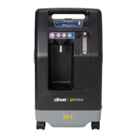
1. Position mounting plates with hooks facing intake side of compressor and
secure with four compressor mounting bolts.
Mounting Plate
Hook
Mounting Plate
Hook
Mounting Bolts
x4
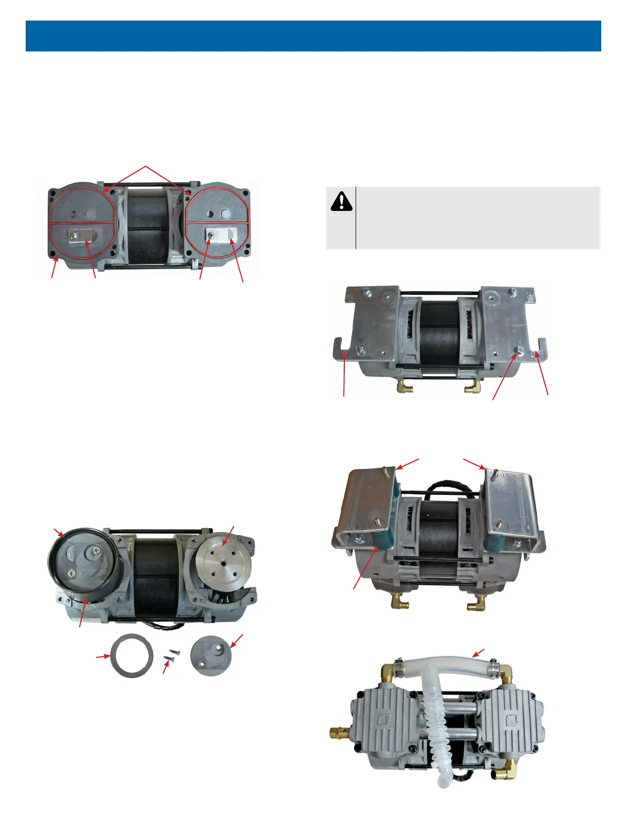
2. Install motor mounts and retaining plates.
Retaining Plates x2
Motor Mounts
x4
3. Turn compressor upright and attach intake hose to both intake ttings.
Intake Hose