LT-2329
20
COMPONENT TESTING, REPAIR AND REPLACMENT
To test the compressor operating voltage:
The compressor requires line voltage to operate. If the compressor does not start
when the unit is turned on, the voltage input must be tested:
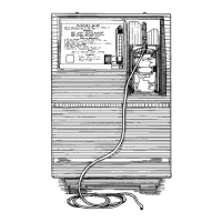
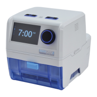
1. This voltage can be checked at the compressor connector using an AC
voltmeter or test light connected to the brown and blue wires. The voltmeter
is the best way to test.
Testing Compressor Voltage
Voltmeter Leads
2. If no voltage is detected, disconnect power and check for loose or broken
wires between the compressor connector and switch or wire harness.
3. If there is voltage at the compressor connector, then either the capacitor or
the compressor itself is defective.
To test the compressor for proper output:
NOTE– If the compressor is not providing a high enough output the patient
alert system may be activated.
1. Use the Cabinet Removal instructions listed previously to open the unit for
testing.
2. Use the Accumulator Pressure Test listed previously to observe the high
pressures, low pressures and the pressure drop.
3. Refer to the Type 1 – Purity Issues, found under Simplied Troubleshooting,
to determine the appropriate action to take in resolving abnormal pressure
cycles.
NOTE– A compressor, which slowly builds pressure that remains below 25
psi, indicates worn cup seals and/ or reed valves.
If these conditions are observed then:
• The unit lter(s) may be occluded—check the air lter, compressor lter,
and intake lter for occlusions.
• There may be a severe leak in the system—check for air leaks using a leak
detection solution such as Snoop
®
or equivalent (must not contain ethylene
glycol).
CAUTION
Do not apply leak test solution to any part of the rotary valve or the
main PC Board assembly.
• The compressor reed valves, cup seal, or the compressor itself may be
defective.
If the lters are not occluded and no leaks are found, the compressor must then
be removed and repaired or replaced.
To remove the compressor:
1. Make sure the unit is unplugged from the wall outlet.
2. Use the Cabinet Removal instructions listed previously to open the unit.
3. Disconnect the compressor wires by disconnecting the compressor
electrical connector.
4. Remove compressor lter by loosening hose clamps and removing hoses
from compressor exhaust tting and heat exchange tube. This can be done
using a 1/4" nut driver or at screw driver.
5. Rotate heat exchange tube to the right 90˚.
6. Disconnect intake hose from intake lter.
7. Carefully lean unit backwards slightly in order to access motor mount nuts
on the bottom. Using a 10 mm nut driver or socket wrench remove the four
motor mount hex nuts.
8. Place unit in upright position and carefully lift the compressor and mounting
plate assembly out of the compressor box.
CAUTION
If the unit has been running recently, the compressor may be hot.
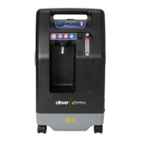
9. Disconnect the intake hose from both intake ttings on compressor.
Intake Hose
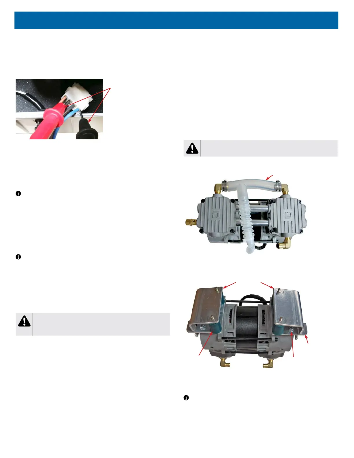
10. Turn compressor upside down and place on work surface.
11. Remove both retaining plates, one on each side of the compressor.
Retaining Plates x2
Motor Mounts
x4
Mounting
Bolts x4
Mounting
Plates x2
12. Inspect motor mounts to see if they are torn or damaged. If necessary,
remove the motor mounts by unscrewing them from the mounting plates by
hand. Install new ones; hand tighten only.
NOTE– If compressor is being replaced, mounting plates need removed. Use
a 3/8" socket to remove mounting plate bolts.