LT-2329
24
COMPONENT TESTING, REPAIR AND REPLACMENT
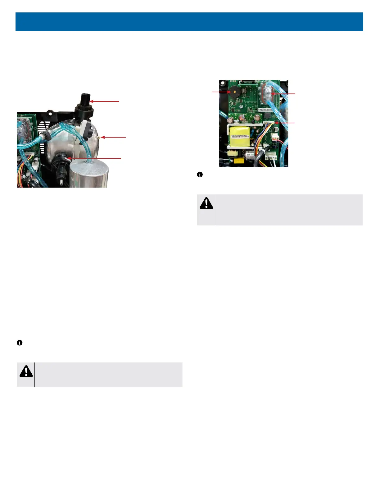
PRESSURE REGULATOR
The 1025 series has two pressure regulators. One regulates the outlet pressure
to the patient and the other regulates pressure to the auxiliary oxygen port. The
regulator located at the top of the accumulator tank is connected to the OSD and
stabilizes the ow of oxygen to the patient and establishes back pressure on the
system. It is pre-set at 20 ± 1 psi (137.8 ± 7 kPA) and should not have to be
adjusted in the eld.
Regulator for Auxillary
Oxygen Port
Pressure Test Point
Regulator for Outlet
Pressure to Patient
It is not necessary to test the pressure regulator unless there is a problem with
ow rate accuracy. The following test is only needed when troubleshooting ow
rate issues.
To test the pressure regulator:
1. Turn the unit “On.”
2. Set the ow meter at 2-3 lpm.
3. Attach a pressure gauge (part #PVO2D-601) to the oxygen outlet to obtain
a reference pressure. Use this reference pressure to determine if further
testing is needed.
4. If the reference pressure varies from the expected pressure by more than ±
1 psi or ± 7 kPa, connect a ‘T’ tting directly between the pressure regulator
tting and the pressure regulator tubing and attach the pressure gauge to
the 3rd leg of the ‘T’ tting. If the pressure reading is not within
20 ± 1 psi (137.8± 7 kPa), adjustment to the pressure regulator is required.
To adjust the pressure regulator:
1. If necessary, the pressure regulator can be adjusted by turning the allen
screw on top of the regulator until the pressure is within specication. Turn
clockwise to increase the pressure, and counterclockwise to decrease the
pressure.
NOTE– Before adjusting the pressure regulator, make sure no leaks exist by
using a certied leak detection solution such as Snoop® or equivalent (must not
contain ethylene glycol).
CAUTION
Do not apply leak test solution to any part of the rotary valve or the
main PC Board assembly.
A malfunction in the pressure regulator will cause either a loss or uctuation in
the oxygen ow which will be seen on the ow meter or a decrease in oxygen
concentration.
To replace the pressure regulator:
1. Make sure the unit is unplugged from the wall outlet.
2. Use the Cabinet Removal instructions listed previously to open the unit.
3. Remove the tubing clamp and tubing from the pressure regulator.
4. Unscrew the regulator from the accumulator tank.
5. Install a new regulator on the accumulator tank and attach the tubing and
tubing clamp.
PRINTED CIRCUIT BOARD
The printed circuit (PC) board is responsible for monitoring and controlling the
Drive DeVilbiss Oxygen Concentrator.
The PC board has preset alerts for low ow and power failure. Should any of the
alert values be exceeded, the patient alert system will activate.
Rotary Valve
Wire Harness
Alarm
OSD
NOTE– If the concentrator has been unused for an extended period, the unit
must run 20 minutes before the power fail alert will be enabled. This alert is
powered by a capacitor on the PC board.
CAUTION
Do not apply any force or ex to the PC Board when connecting or
disconnecting electronic or pneumatic components. Damage to the
electronic assembly is possible.
To remove and replace the PC board:
1. Make sure the unit is unplugged from the wall outlet.
2. Use the Cabinet Removal instructions listed previously to open the unit.
3. Disconnect all wires and electrical connectors.
4. Remove the 1/8" (3.2mm) tubing from both ttings on the oxygen sensor.
5. Remove the screw that secures the board to the unit and remove the PC
board.
6. Install the new PC board and secure it using the screw.
7. Reconnect all electrical wires, connectors and the tubing to the sensor.