LT-2329
8
MAINTENANCE
PATIENT ALERT SYSTEM
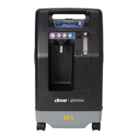
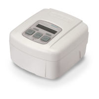
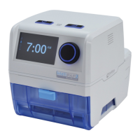
The Drive DeVilbiss Oxygen Concentrator patient alert system will detect unit
component failure. This system is comprised of both visible and audible alerts
which signal the patient if a malfunction should occur.
DeVilbiss OSD
®
Operation
The OSD is a device within Drive DeVilbiss concentrators that monitors the
oxygen produced by the unit. The OSD operates as follows:
• Normal Oxygen (green light) - oxygen purity normal
• Low Oxygen (yellow light) - oxygen purity low–requires servicing
NOTE– If the oxygen purity continues to fall, an audible signal will sound
intermittently. If the oxygen purity continues to fall to a low enough level, the
yellow “Low Oxygen” light will remain on and the red “Service” light will also turn
on.
NOTE– Refer to the Alerts section below for specic alert settings.
NOTE– After power on, the electronics continuously monitors the oxygen
sensor. If a fault is detected, the green "Normal Oxygen" light will turn off and
the beeping audible alert and blinking red "Service Required" light will activate.
The rst 15 minutes, the unit will be in “Start Up” mode. The oxygen purity is
continuously monitored and the green "Normal Oxygen" light will turn on as
soon as the therapeutic oxygen levels are obtained. After 15 minutes
stabilization time, if the O
2
is less than 85% the yellow Low O
2
LED will be on
and a beeping audible alarm will occur. If the level is below 60% (after startup)
then the yellow and red LEDs will be lit along with a beeping audible alarm. The
audible low O
2
alarms are blocked during the 15 minute stabilization delay and
also during the 10 minute stabilization delay that occurs during turn-down mode
enter/exit.
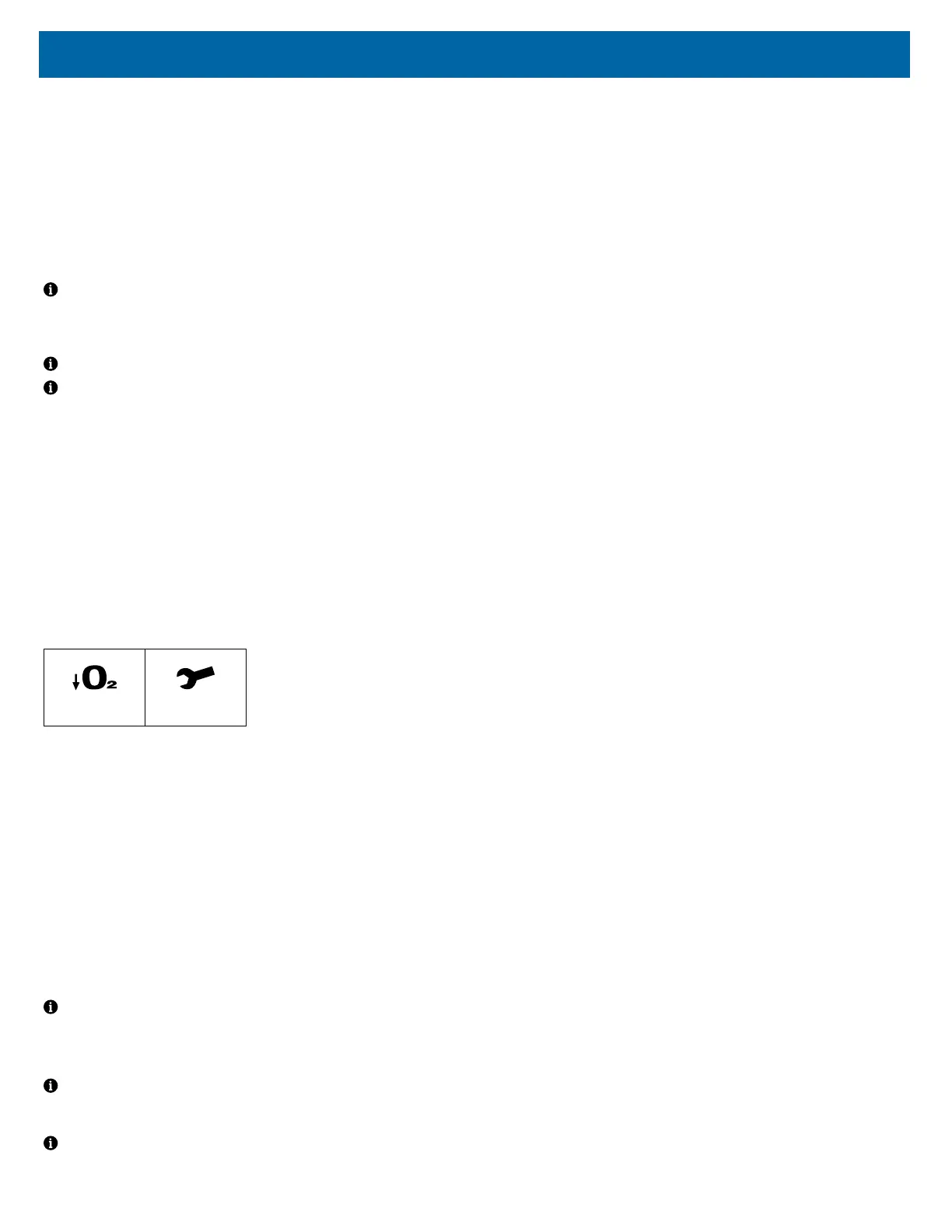
Alerts:
There are two visible service alerts located on the front panel.
Low O
2
%
Service
The audible alert system is internally powered; no batteries are required. If the
indicator lights illuminate or the audible alert sounds other than during start-up,
a problem has occurred
• Power Failure (Pulsing audible alert)
• Low Flow (Below 2 lpm) (Continuous red “Service” light and audible alert)
Below normal O
2
:
• The yellow Low Oxygen light will illuminate with an audible alarm at
approximately <85%.
• The yellow Low Oxygen and red Service Required lights will illuminate with
an audible alarm at <60%.
The audible alert will activate for a minimum of two minutes in a no power
situation. There is no visual indicator for this alarm. If the unit is turned “On”
without power or power is removed later, the alert will sound within 10 seconds.
After that time, the alert will produce an audible pulse every few seconds. Power
for this alert is provided by a capacitor on the PC board.
NOTE– If the concentrator has been unused for an extended period, the unit
must run several minutes before the power fail alert will activate.
The PC (printed circuit) board is responsible for controlling the system and
alerts.
NOTE– A high pressure condition is indicated by the audible (a “popping”
sound) release of pressure from a pressure relief valve located on the
compressor head.
NOTE– Settings below 2 LPM may activate the low ow alarm. Do not use a
low-output ow meter with this concentrator.
ALARM FUNCTION TESTING
The 1025 series is designed to activate alarms when certain conditions or
failures occur. The alarm functions may be tested following the procedures
below:
1. Overheating:
a. Remove the front and rear covers from the concentrator; then
disconnect the cooling fan from the printed circuit board.
b. Replace the front and rear covers.
c. Place the concentrator in a location that has an ambient temperature
of approximately 70° F. Then plug the unit into the appropriate mains
voltage and turn it on.
d. Allow the unit to operate until the Service Required Alarm activates,
which should be within approximately two hours.
2. Compressor Failure:
a. Remove the rear cover from the concentrator; then disconnect the
compressor electrical connector from the main wire harness.
b. Plug the unit into the appropriate Mains voltage and turn it on.
c. Allow the unit to operate until the Service Required Alarm activates,
which should be within approximately two minutes.
3. Low Flow / Obstruction of Gas Pathway:
a. Plug the concentrator into the appropriate mains voltage and turn it
on.
b. Allow the device to run for several minutes.
c. Turn the ow meter off so that there is no oxygen owing out of the
unit.
d. Allow the unit to operate until the alarm condition occurs (red light
and audible beep).
e. Increase the ow to 2 LPM and conrm that the alarm condition
ends.
4. High Flow
a. Connect the oxygen concentrator to AC power and turn the power
switch on.
b. Allow the device to run for several minutes.
c. Adjust the output ow to more than 11.0 LPM using the ow meter
knob (turn counter clockwise until ball goes above 11.0 LPM).
d. The alarm condition (yellow light) should occur.
e. Decrease the ow to 10 LPM and conrm that the alarm condition
ends.
5. Oxygen Generation Mains Failure:
a. Plug the concentrator into the appropriate mains voltage and turn it
on.
b. Turn the ow meter to 10 LPM.
c. Attach another ow meter to the auxiliary oxygen port which is
located on the rear of the concentrator and then adjust the ow to 3
LPM.
d. Allow the unit to operate until the Service Required Alarm is
activated, which should be within approximately thirty minutes.
6. Pressure Failure:
a. Remove the front and rear covers from the concentrator.
b. Disconnect the tubing from the top of one of the sieve beds.
c. Plug the unit into the appropriate mains voltage and turn it on.
d. Turn the ow meter to 10 LPM.
e. Allow the unit to operate until the Service Required Alarm is
activated, which should be within approximately thirty minutes.
7. Power Supply Failure
a. Connect the oxygen concentrator to AC power and turn the power
switch on. Allow the device to run for several minutes.
b. With the power switch in the on position, unplug the AC power cord
from the outlet.
c. The alarm condition (audible beep) should occur and continue for a
minimum of 120 seconds. There is no visual indicator for this alarm