17
LT-2329
COMPONENT TESTING, REPAIR AND REPLACMENT
PROPER REPAIR PROCEDURES
WARNING
When servicing the Drive DeVilbiss Oxygen Concentrator, be
absolutely certain that the correct tools are used and that the parts
are free of oil and grease or any material not compatible with oxygen.
Teon
®
tape is recommended and must be applied to the male
threads omitting the rst thread to eliminate the possibility of tape
particles entering the oxygen system.
Electric shock hazard. Do not remove cabinet. The cabinet should
only be removed by a qualied Drive DeVilbiss homecare provider.
Disconnect the power cord from the wall outlet before attempting
repairs on the unit. Extra care should be taken if it is necessary to
operate the unit with the cabinet removed.
NOTE– Be sure to read all of the steps involved before beginning any of the
procedures in this manual.
NOTE– After repairing or replacing a component, run the unit for 20 minutes,
check the oxygen concentration and test for leaks.
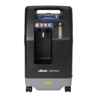
The DeVilbiss Oxygen Concentrator is designed for ease of service. To aid
service personnel a Service Kit (part #444-501) is available which contains the
necessary gauges, tools, and testing instruments to properly service the oxygen
concentrator. See list below.
In addition, you will also need an oxygen analyzer (part #R217P62) to
periodically check oxygen concentration levels and leak test solution.
The following parts are included in the Service Kit:
1 Slotted bit
1 #1 Phillips bit
1 #2 Phillips bit
1 Crescent wrench
1 8” Duckbill pliers
1 Voltmeter
2 Pressure/Vacuum gauge
1 Tool box
2 Test Fittings
1 Torx screwdriver w/bits
1 Channel Lock Pliers
1 1/4” Ratchet wrench
1 10mm Socket l/4” Drive
1 1/4” Drive extension
1 Plastic storage case
CABINET REMOVAL
The majority of all the servicing and repairs can be done without removing the
front cabinet completely. However, it may be loosened or removed to gain access
to the components behind it.
To remove back cabinet:
1. Unplug the unit from the wall outlet.
2. Remove the six screws that secure the back cabinet – 2 behind handle, 2
near the bottom, and 1 on each side.
NOTE– All six screws are the same size.
3. Remove the back cabinet by sliding it toward the rear until clear.
4. To reassemble, reverse steps 2-3.
To loosen the front cabinet:
5. Remove the two screws (located directly above the intake bacteria lter)
that hold the front cabinet to the unit’s internal structure.
6. Remove the screw located near the bottom of the recessed humidier
compartment on the front of the unit. The top of the front cabinet can now
be tilted forward to allow access to the components behind it.
To remove the front cabinet completely:
7. Tilt cabinet forward.
8. Before disconnecting the wires from the power switch and circuit breaker
note their positions in order to reconnect them properly; then disconnect the
wires.
9. Disconnect the hose at the bottom of the ow meter and remove cabinet.
10. To reassemble reverse steps 5 – 9 making sure bottom of cabinet is
inserted securely in base of unit.
NOTE– Two types of cabinet screws are used in the 1025 models, thread-
forming screws and machine screws. Do not overtighten the thread-forming
screws; they should be torqued to 18 –20 in-lbs. The machine screws have much
ner threads and are used in conjunction with brass inserts that are molded into
the cabinet part; they should be torqued to 20 – 25 in-lbs.
When replacing a cabinet part such as the front cover, base or compressor box
be sure to use the correct screw. The ne threaded machine screws should
always be used if there is a brass insert. Thread-forming screws should be used
if there is no brass insert molded into the cabinet part.
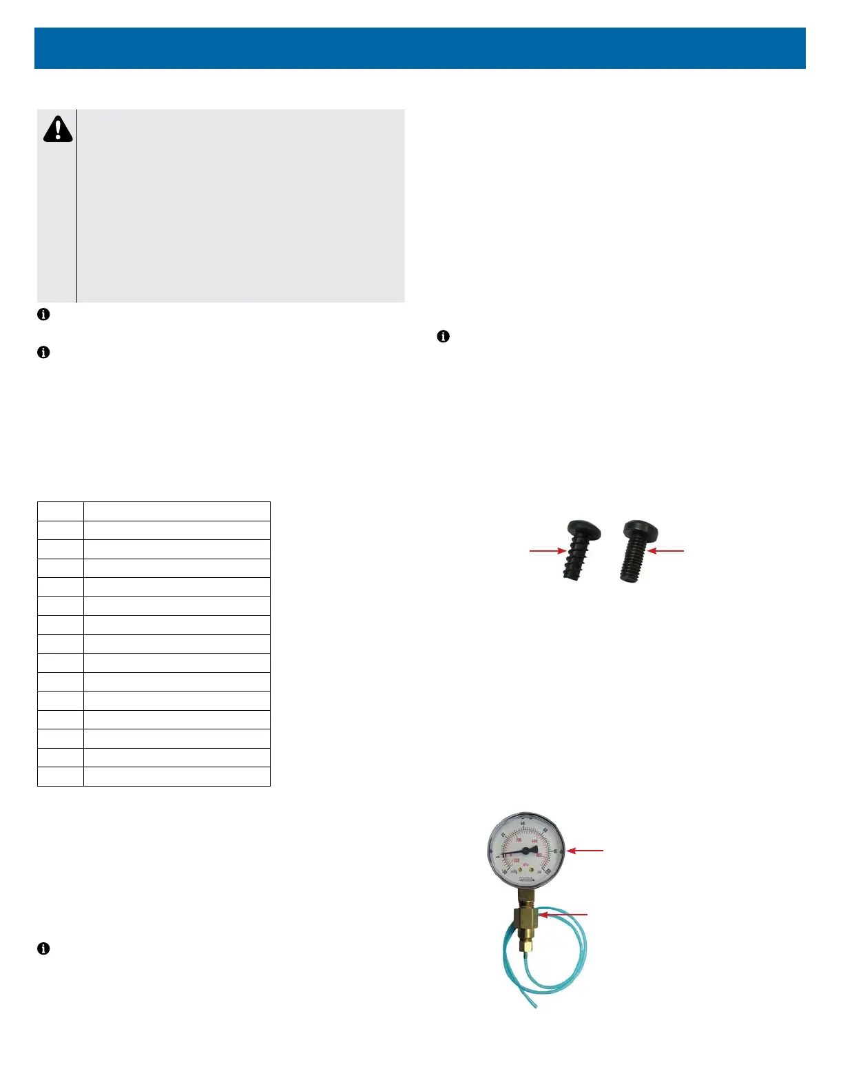
These screws are not interchangeable, so be sure to order the correct part
number. See gure below.
Thread-forming
Cabinet Screw
(525DD-636)
Machine Cabinet
Screw (525DD-628)
ACCUMULATOR TANK
The oxygen accumulator tank holds the concentrated oxygen and releases it to
the patient at a specied liter ow.
ACCUMULATOR PRESSURE TEST
To check accumulator pressures:
1. Make sure the unit is “Off.”
2. Use the Cabinet Removal instructions listed previously to open the unit for
testing.
3. Use the pressure gauge (part #PVO2D-601) and pressure test assembly
(part #303DZ-637) included in the Service Kit.
Pressure Gauge
Pressure Test
Assembly