LT-2329
18
COMPONENT TESTING, REPAIR AND REPLACMENT
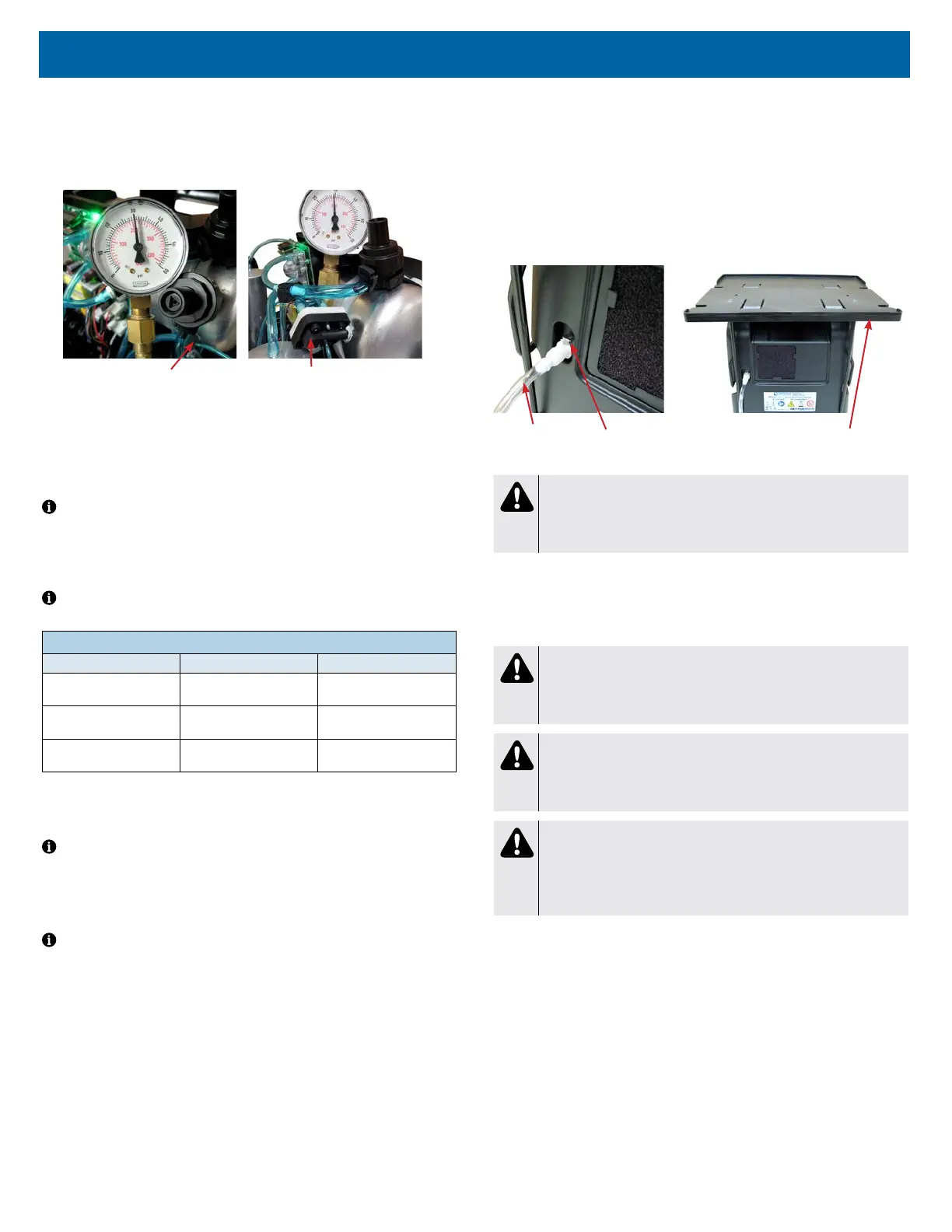
4. Remove the tubing cap from the accumulator tank tting or from the
manifold attached to the tank, and attach the 1/16" (1.6 mm) diameter
tubing from the gauge to the tting just vacated above.
See Figures below showing pressures being checked at accumulator tank
"T" tting and manifold.
Accumulator "T" Fitting Manifold
5. Turn the unit “On” with the ow rate set to maximum recommended ow,
which is 10 lpm. Allow the unit to run for 5 minutes before observing the
pressures. During each timed cycle, the average pressure in the oxygen
accumulator will rise and fall. The high pressures should be consistent and
the low pressures should be consistent. The pressure swing will be
approximately 4-5 psi.
NOTE– Expected normal pressures observed depend on altitude and ow
rate. See the Typical Peak Accumulator Tank Pressure Range chart below.
• Increases in altitude and ow rate will slightly decrease accumulator
pressures.
• Lower altitudes and ow rates will slightly increase accumulator pressures.
NOTE– A defective check valve in the purge harness may cause a rapid drop
in accumulator pressure below the minimum value.
TYPICAL PEAK ACCUMULATOR TANK PRESSURE RANGE @ 10LPM
Altitude Psi kPa
0 to 457 m
0 to 1500 ft.
25-36 172-248
457 to 914 m
1500 to 3000 ft.
21-33 145-228
914 to 1524 m
3000 to 5000 ft.
21-30 145-207
6. Refer to the Type 1 – Purity Issues, found under Simplied Troubleshooting,
to determine the appropriate action to take in resolving abnormal pressure
cycles.
NOTE– A defective compressor will be indicated by slowly rising pressure.
Pressure may only reach a certain level and then stop.
Low oxygen concentration levels and accumulator pressures higher than normal
may indicate defective sieve beds. Severely contaminated beds may also cause
the pressure relief valve on the compressor to open.
NOTE– A malfunctioning rotary valve may also cause high accumulator tank
pressure and activation of the pressure relief valve. In this case it should be
determined whether the problem is with the sieve beds, valve, or both.
AUXILIARY OXYGEN PORT
All 1025 series concentrators are manufactured with an auxiliary oxygen port
located on the back of the unit.
To ll oxygen cylinders:
This external port can be used to ll oxygen cylinders with an FDA-cleared
cylinder lling device that is designed to use oxygen from a concentrator to
ll a cylinder. The port is only for use with FDA-cleared lling devices with
compatible oxygen input specications.The ow meter should be set at 6
LPM or less when the concentrator is being used during cylinder ll. The
port does not affect concentrator performance if properly used. See gures
below.
Auxiliary Port Output Specications:
Outlet Pressure ........................................ <15 psi
Outlet Flow ............................................. 2.0 LPM
Outlet Oxygen ..............................................>90%
Operation Time ................................... Continuous
Refer to the cylinder lling device instruction guide for the oxygent input/output
specications, connection and operating instructions.
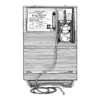
Transfill Hose
(PF1100TUB)
Auxiliary Port
Transfiller Caddy
(525DD-650)
WARNING
When using the Transller Caddy with a Transll device, always keep
the system on a at surface. Disassemble the system prior to
moving.
CAPACITOR
The capacitor enables the compressor to start and run by supplying voltage to
the windings of the compressor motor. A defective capacitor will result in the
compressor running slower or not starting.
CAUTION
The 1025DS concentrators use a GSE compressor with a 60 mfd
capacitor. If replacement is necessary, be sure the correct capacitor
is installed.
CAUTION
The 1025KS/1025UK concentrators use a GSE compressor with a
17.5/15 mfd capacitor respectively. If replacement is necessary, be
sure the correct capacitor is installed.
WARNING
Electric Shock Hazard. When replacing the capacitor, do not touch
the terminals or allow metal objects to come in contact with the
terminals on the capacitor. The capacitor may hold a charge for
several days after the unit is turned off.
If a defective capacitor is suspected, a new one must be installed. The capacitor
is located beside the intake lter or next to the cooling fan in the base of the unit.
To replace the capacitor:
1. Make sure the unit is unplugged from the wall outlet.
2. Remove the back cabinet and also loosen the front cabinet and tilt it
forward. Use the cabinet removal instructions listed previously.
3. Disconnect the two wires from the terminals on the capacitor.
4. Cut the nylon cable tie holding the capacitor in place and remove the
capacitor.
5. Install the new capacitor and secure with a new cable tie.
6. Reconnect the wires to the new capacitor.
7. Replace both cabinets and secure with screws.