Vacuum Breaker (also called an air gap)
In the left rear of the cabinet is the vacuum breaker. It guides the water to the tub and dispenser and prevents
a back ow of water.
Water Valves
Remove top panel to access water valves. (see Removing Top Panel) The two dual outlet water and/or
single coil valves are mounted to the rear channel with two screws each. Always check inlet screens to be
sure that they are clean. Disassembly requires the removal of two solenoid screws and three valve body
screws. Below the solenoid coil is a solenoid guide, armature, armature spring and diaphragm. All valve
parts are available individually or as a complete unit.
Door Lock Assembly Operation
After loading the clothing, the door should be closed and latched. The locking cam on the door contacts
the latching switch actuator which closes the latching switch. The specied number of coins should now be
added to start the washer. The solenoid pulls up on the locking pawl by use of a linkage rod. The locking
pawl has two jobs. The rst is to lock the door. This is accomplished by blocking the locking cam on the
door so that it can’t rotate to unlock. The second job is to close the two piggyback lock sensing switches.
These switches control power to all of the controls. If the door unlocks for any reason, these two switches
will stop the machine. When the door handle is 1/4 to 1/2 of an inch from its fully closed position, the
latching switch should close. The two piggyback lock sensing switches should be open when the door is
unlocked and should be closed when the door is locked.
Accessing the Door Lock Assembly
After removing the front panel and masking ring, the door lock assembly can now be accessed.
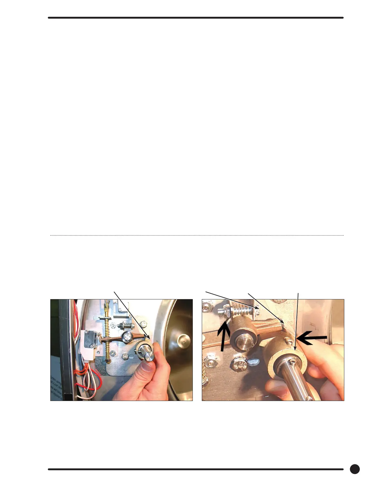
Adjustment for Door Lock Assembly
Step 1: Set door cam over pin. Here you can see
the door cam away from the door lock
assembly.
Step 2: Tighten spring screw on switch actuator
bracket arm until it just clears cam OD. at
base of door lock assembly.
Adjustment to this bracket usually
is not necessary as next step is used
more in eld.
43
Part # 8533-083-001 1/18
Spring screwJust clear here
Switch actuator
bracket
Door cam sample
 Loading...