Electronic Control Diagnostic Lights
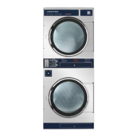
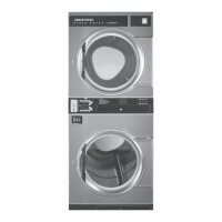
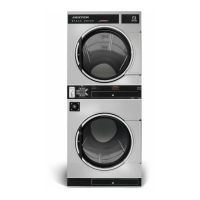
The electronic control has 6 diagnostic lights to aid in service of the dryer. Each pocket has indicator lights for
the motor circuit, door switch circuit, and the heat circuit. When the electronic control is carefully unlocked
and moved forward these lights are visible on the circuit board. They are each labeled as to function indi-
cated.
1. When either dryer door is closed, the appropriate door light on the computer should be
illuminated indicating that the door is closed.
2. When either dryer is running, the appropriate motor light on the computer should be illuminated
indicating that the computer is calling for the motor to operate.
3. When either dryer is calling for heat, the appropriate heat light on the computer should be
illuminated indicating that the computer is calling for heat.
An example of their function would be troubleshooting an upper dryer pocket that did not heat.
1. Start the machine and insure that it did not heat.
2. Check the upper heat light and see if it is lit.
3. If the heat light is on, this would indicate that the computer was calling for heat and that it was
not at fault. You would then go on to check the rest of the heat circuit.
Electronic Control Test Cycle
This test cycle allows the dryer to run for 5 minutes without the need for adding money while servicing. To
actuate this 5 minute test cycle enter into the Programing mode and enter into Quick Test.
Electronic Control Removal
Unlock the retaining lock in the control assembly. Slide the control out of the machine holding the control
by the metal tray. There is enough wire length to allow removing the control tray from the machine before
disconnecting the wires.
Membrane Switch Replacement
The control buttons are an adhesive membrane switch assembly which may be replaced separately. Slide
the control out to gain access to disconnect the ribbon connector. The ribbon connector must be pushed
solidly and squarely into its connector when connecting a new membrane switch.
Temperature Sensor Testing
If either tumbler display shows an F1 or F2, that is an indication of possible temperature sensor problems
for that tumbler. Before replacing a sensor, check the wires and connections of the sensor for damage.
The sensor lead wires are very small and care should be used in routing and connecting them. The
sensors are located under the tumblers and may be viewed by removing the lint screen. The temperature
sensor should have between 30,000 ohms and 60,000 ohms resistance at room temperature if okay.
Temperature Testing
To check the temperature in the dryer tumbler, press and hold the upper or lower start button for the
tumbler being checked and while holding the start button also press the temperature button for the
temperature to be checked. The display will read out the current temperature.
60
Part # 8533-090-001 7/21

 Loading...

