Door Locking Solenoid
The door locking solenoid is powered shut with control voltage to lock the door and releases
when voltage is removed. It is located in the left front corner of the washer.
Thermoactuators
The thermoactuators are a safety device that keeps the door from immediately unlocking if
power is lost while the machine is operating. They are mounted under the door locking solenoid.
Lock Thermoactuator
Control voltage is applied to the lock thermoactuator at the beginning of the cycle making it extend and
block the door locking solenoid. This keeps the door locked for approximately two minutes after a power
failure occurs. The lock thermoactuator does not delay the door opening at the end of a normal cycle.
Unlock Thermoactuator
To ensure that the lock thermoactuator has retracted by the end of the cycle, one minute prior to the end
of the cycle, the unlock thermoactuator is powered with control voltage making it extend and unblock the
door locking solenoid.
Loading Door Removal
A. Support door to prevent dropping.
B. Remove 3 bolts holding hinge retainer and set door o.
Loading Door Disassembly
A. Remove the loading door as outlined above.
B. Lay the door on a at surface with the glass down.
C. While holding down on the door glass, lift up on the door ring and roll back the lip of the
gasket with your ngers.
D. Work all the way around the gasket and the glass is out.
Loading Door Reassembly
A. Lay the door ring face down on a at surface.
B. Start the glass into one side of the door. gasket.
C. Use one hand underneath to push the gasket out and the other hand on the top pulling
the gasket in place.
D. The front lip of the door gasket should be checked for proper seating.
Loading Door Adjustment
The door can be adjusted by changing the number of shims behind the door hinge and the
door lock assem bly. The vertical t of the door to the tub can be altered by loosening the door
hinge bolts and raising or lowering the door before retightening. It is important for the door to
be centered on the tub front. By chalking the nose of the tub and closing the door to transfer
that line to the gasket, the centering can be evaluated. It is also important for door pressure to
be similar around the door perimeter. Door pressure can be evaluated by inserting a dollar bill in
several positions and tugging on it. See Parts Section for kit to increase door sealing
pressure.
Loading Door Hinge Removal
A. First remove loading door, front panel, and trim ring.
B. Remove 3 screws holding door hinge. Shims may be present between hinge and tub front.
The number may be increased or decreased to adjust right side door pressure.
NOTE: Door hinge mounting bolts penetrate tub front and require silicone sealer applied to holes
when reinstalling.
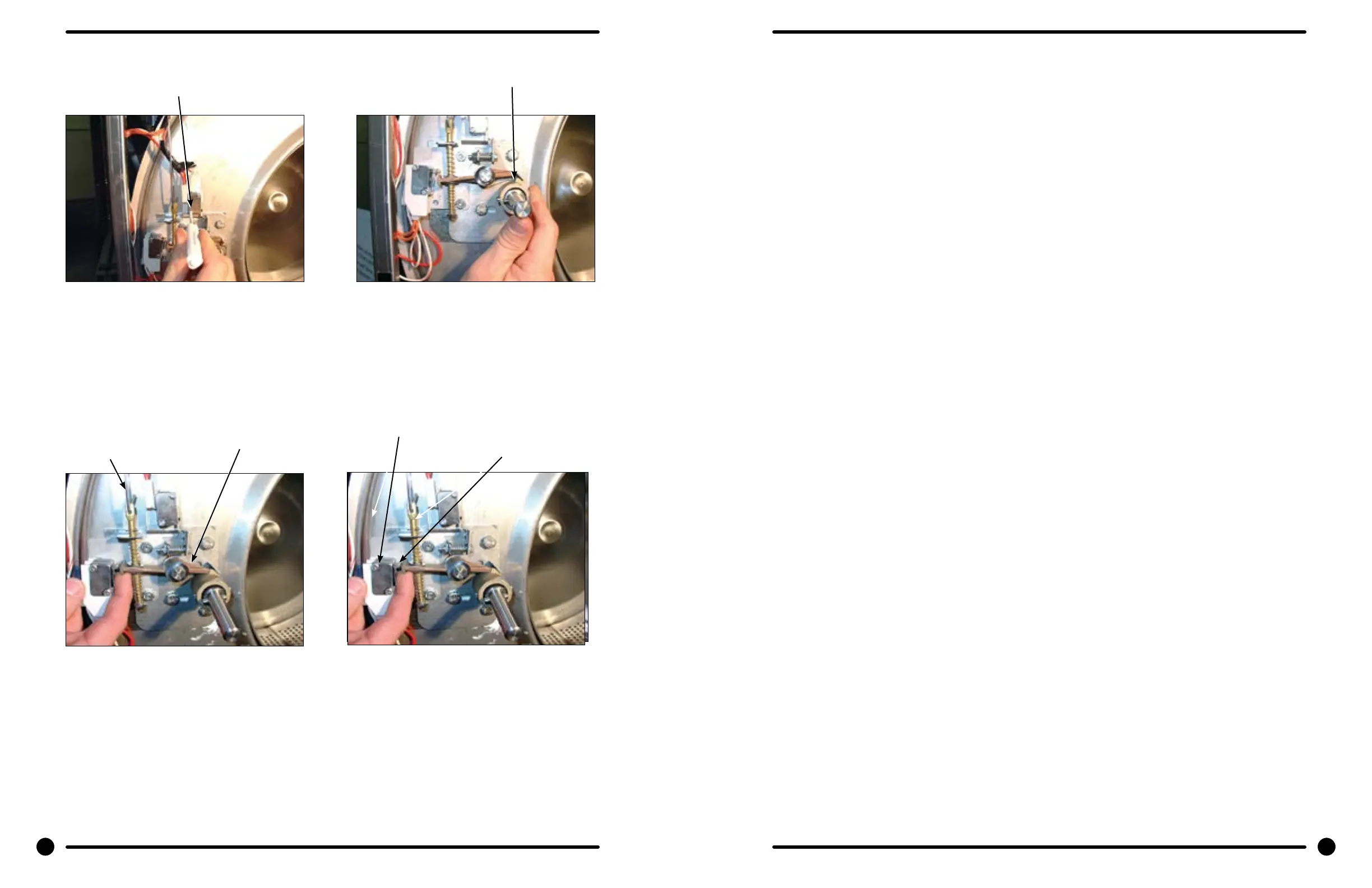
Step 4: Check for switch actuation at partial
turn of cam as in operation above. Door
handle goes from horizontal to six o’clock
vertical.
Step 3:
With switch actuator bracket adjusted you
will now need to adjust single switch by
loosening 2 at brade screws and allowing
swivel of switch. Move switch towards above
bracket until it actuates. Now tighten at
blade screws. Use a .040 thickness guage to
insert between bracket and switch and the
switch should close and open again upon
removal of thickness guage.
Step 5: Check that lock pawl arm swings to cam
lobe to lock position.
Step 6: The lock stacked switches (piggyback)
must be adjusted as door lock solonoid
pulls up on door rod and locking pawl is
now blocking door cam from turning and
is in full up position. The stacked swtiches
(piggyback) have a single actuator arm
and it must actuate when single actuator
roller wheel rolls to at side of locking
pawl. You will also notice a .040 gap
between actuator arm and switch bodies.
Note: Both stacked switches must operate
together!
44 45
Part # 8533-035-002 4/22 Part # 8533-035-002 4/22
Flat blade screw on
door switch latching
Door lock rod
Locking pawl blocking
Adjustment screw for
(piggyback switches)
Top at end of
locking pawl.
Door cam
check position