Tub Back, Bearing and Cylinder Assembly
Basket assembly T-400 & T-600
Reassembly
Reverse the procedures to the left
paying attention to the following
areas
Step 1: Lay the washer on its front.
Note: Put a thick pad across
the front of the washer,
above the door, to protect
the handle and coin acceptor.
Step 2: Make sure the bearing
housing weep holes are
located at 12 o’clock and 6
o’clock.
Step 3: Clean the silicone rubber
from the back of the outer
tub and the perimeter of
the tub back where the two
meet. There is no gasket in
this area.
Step 4: Apply a new bead of silicone
rubber around the back of
the outer tub. (see picture)
Step 5: Lower the tub back, bearing
and cylinder assembly into
the washer outer tub.
Step 6: Torque all bolts according to
the following charts.
Step 7: Use a puller to remove the
pulley from the shaft.
Removal
Step 1: Remove the top and back panel as described.
Step 2: Move the rear channel, that the water valves mount to,
forward by removing the ve mounting screws.
Step 3: Remove the drive belt.
Step 4: Remove the overow hose, tub ll hose and pressure
switch hose from the back of the tub.
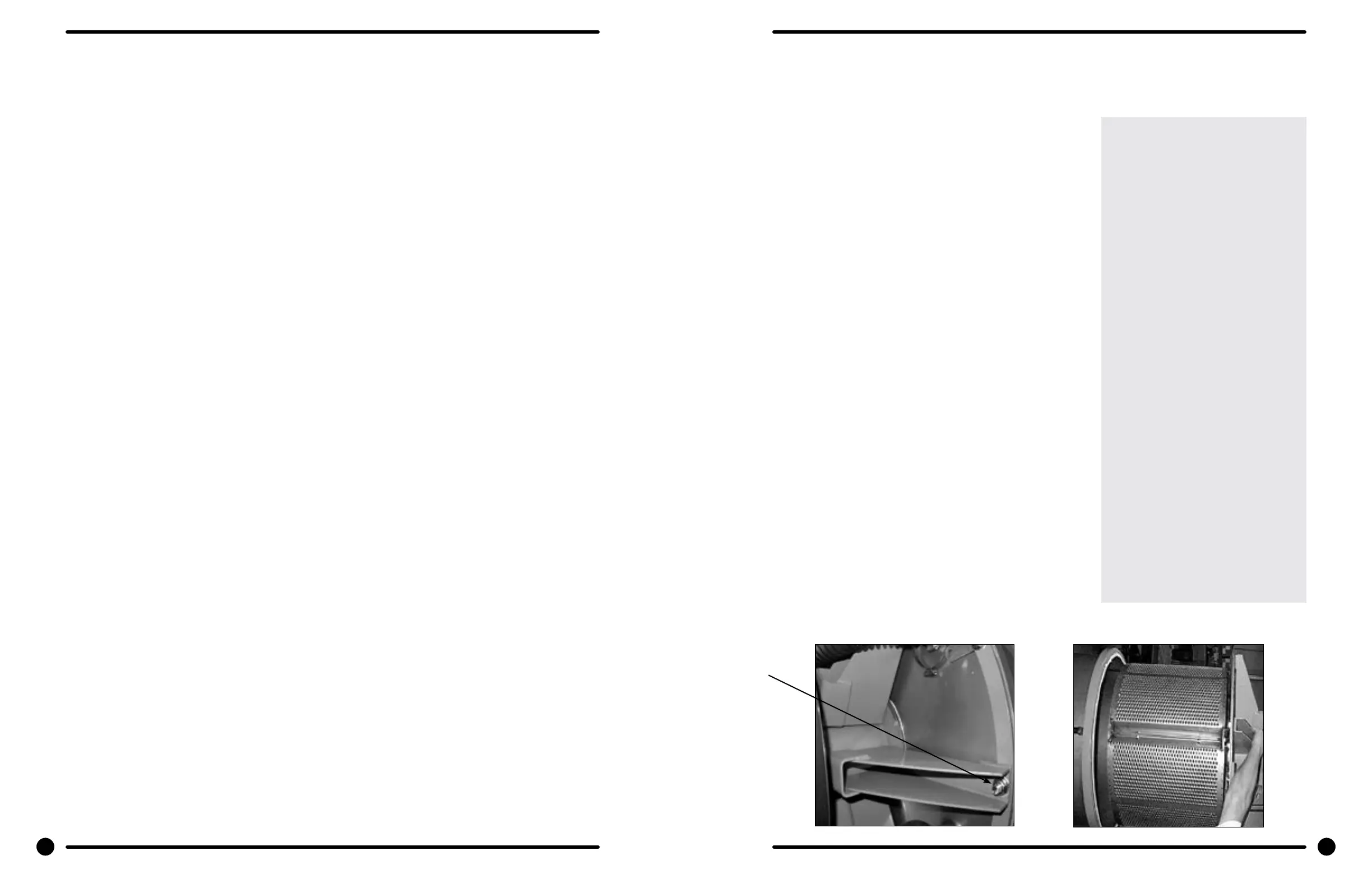
Step 5: Mark the tub back and bearing assembly for ease in
assembly later. (see picture)
Step 6: Remove the 12 bolts and nuts from the perimeter of
the tub back clamp ring. (Two of the twelve bolts are
longer and go through the thicker part of the brace
where it connects to the frame.)
Step 7: Remove the 2 bolts that fasten the clamp ring to the
frame.
Step 8: The entire tub back and cylinder assembly may be
lifted out of the tub (it may be necessary to break the
adhesion of the silicone that seals the tub back to the
tub). Blocks should be placed under the edges of the
cylinder before setting it down to prevent damage to
the cylinder ange.
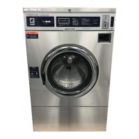
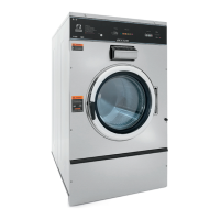
Outer Cabinet Removal
T-400 & T-600
Removal of Cabinet T-400 & T-600
Step 1: The power supply, water hoses, and drain connection must all be disconnected before proceeding
with the disassembly.
Step 2: Now remove the lower service panel and the top panel assembly.
Step 3: Remove the left and right lower front panel screws that retain the panel to the chassis.
Step 3: Remove the bottom row of back panel screws.
Step 4: Remove the loading door.
Step 5: Remove the screws along the bottom of each side panel. When reinstalling these screws do not
overtighten.
Step 6: Remove clamp and soap dispenser hose where it attaches to the tub inlet. Disconnect the door lock
wires from all switches and the door lock gear motor.
Step 7: Disconnect pull rod between gear motor and door lock assembly. Disconnect the wires to the dump
valve at the bottom of the machine.
Step 8: Disconnect the wires to the drive motor from the VFD T1, T2, T3.
Step 9: Remove the clamp and the hose from the vacuum breaker where it connects to the inlet on the back
of the tub.
Step 10: Remove the pressure switch hose from the bottom of the switch.
Step 11: It should now be possible for two people to lift the cabinet up and o of the front of the machine and
set it aside.
Outer Tub
Removal
Step 1: The outer tub can easily be removed when the tub back, bearing, and cylinder assembly have been
removed as outlined.
Step 2: At that point only attachments to the chassis are the two front strap mounting bolts.
Reassembly
Step 1: Install outer tub in front strap leaving bolts loose.
Step 2: Install tub back assembly in washer (see Reassembly of Tub Back, Bearing, and Cylinder (basket)
Assembly).
Step 3: With tub tback assembly bolted to washer frame and to the back of the outer tub, tighten front strap
bolts.
50 51
Part # 8533-035-002 4/22 Part # 8533-035-002 4/22